Airfoil profile with optimized aerodynamic shape

a technology of aerodynamic profile and airfoil blade, which is applied in the field of aerodynamic profile of airfoil and airfoil blade, can solve the problems of reducing the aerodynamic efficiency of airfoil, reducing the aerodynamic efficiency and the ability to discharge combustion gases in sufficient volume, and affecting the aerodynamic efficiency of airfoil, so as to improve the aerodynamic efficiency of the turbine, improve the aerodynamic performance, and reduce the loss of airfoil

Active Publication Date: 2006-08-22
RTX CORP
View PDF8 Cites 45 Cited by
  • Summary
  • Abstract
  • Description
  • Claims
  • Application Information

AI Technical Summary

Benefits of technology

[0008]In accordance with an embodiment of the present invention, there is provided an airfoil profile, preferably for a first stage turbine blade, that improves the aerodynamic efficiency of a turbine. The profile also improves the first blade's interaction with a first and second stage vane for improved aerodynamic performance and reduced airfoil losses. Further, the profile allows for an increased coating thickness, without reducing the area between adjacent airfoils and the volume of combustion gas that may be directed rearward. The area between coated airfoils is maintained by rotating each airfoil to increase the area, thus counteracting the area lost by the increased coating thickness. In addition, the airfoil profile eliminates sources of performance penalties such as flow separation, separation bubbles, shock waves, leading edge overspeed and increased surface velocities.
[0010]A gas turbine blade in accordance with an embodiment of the present invention improves the aerodynamic efficiency of a turbine, and the area between coated airfoils is maintained by rotating each airfoil, thus counteracting the area lost by the increased coating thickness. The blade comprises a nominal airfoil profile in accordance with the coordinates of Table 1 and may be uncoated or coated to suit a specific turbine application.

Problems solved by technology

The addition of thicker coatings to an airfoil may negatively affect the aerodynamic efficiency of an airfoil and specifically, an airfoil's ability to direct an adequate volume of combustion gases rearward.
By increasing an airfoil's coating thickness, the area between adjacent airfoils is decreased; therefore, reducing the aerodynamic efficiency and ability to discharge an adequate volume of combustion gases.

Method used


Image

  • Airfoil profile with optimized aerodynamic shape
  • Airfoil profile with optimized aerodynamic shape
  • Airfoil profile with optimized aerodynamic shape

Examples


Embodiment Construction

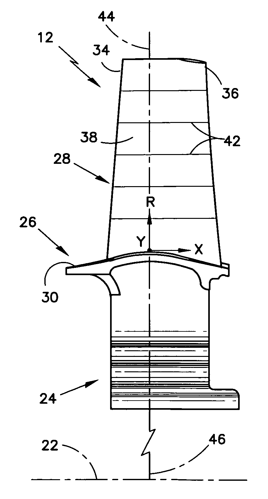
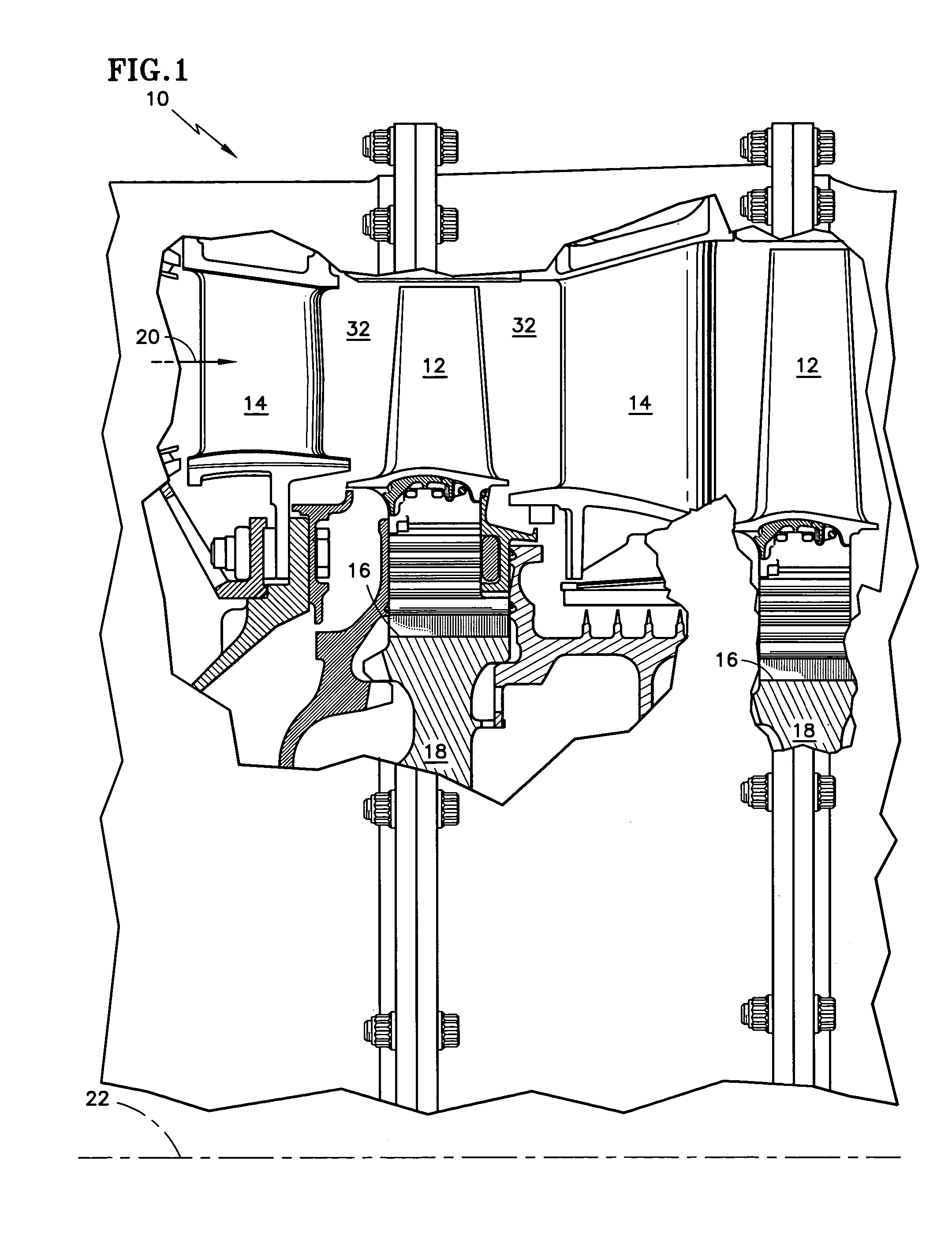
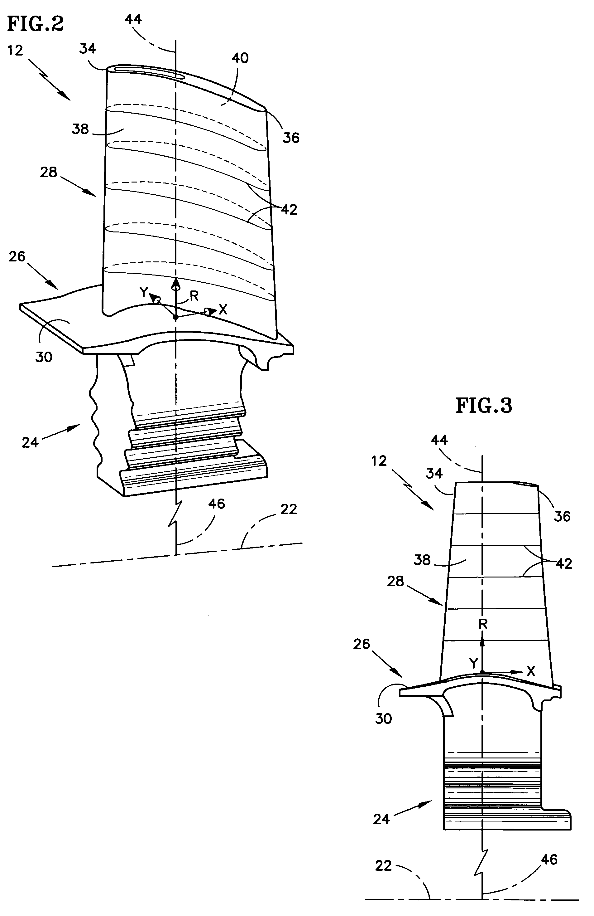
[0014]A high-pressure turbine 10 of FIG. 1 includes alternating stages of rotating blades 12 and stationary vanes 14. The blades 12 of each stage are circumferentially disposed about a radially outer rim 16 of a disk 18. The blades 12 may be integrally formed with the disk 18 or may fit within spaced, fir tree slots directed axially through the thickness of the rim 16. The blades 12 extract power from combustion gases 20 and transfer the power to the disks 18, which rotate about a central axis 22 of the turbine 10. In order to protect the blades 12 from the hot combustion gases 20, internal cooling passages and thermal barrier coatings are typically utilized. Coating thickness is increased in the areas of the blades that are exposed to the combustion gases and have limited life. In the example shown, the blades 12 are disposed axially between the vanes 14 and interact aerodynamically therewith to provide optimum turbine 10 performance and efficiency. It is to be understood that the ...


PUM


Abstract

Provided is an aerodynamic profile for use in gas turbine airfoil and a turbine blade comprising such profiles. The profiles counteract a reduction in area between adjacent airfoils due to an increase in coating thickness. A plurality of radial sections forms both coated and uncoated nominal profiles of the airfoils. The sections are located within a tolerance measured in any direction perpendicular to an airfoil stacking line extending radially from a central axis and defined by X, Y, and R Cartesian coordinate values in inches. The R values are measured perpendicular to a plane normal to the airfoil stacking line with R values of zero at a lowermost radial section and increasing in the radial direction. The X and Y values are measured perpendicular to the airfoil stacking line.

Description

CROSS-REFERENCE TO RELATED APPLICATIONS[0001]This application discloses subject matter related to co-pending US applications “COOLED ROTOR BLADE” Ser. No. 10 / 855,188, “COOLED ROTOR BLADE” Ser. No. 10 / 855,049, “COOLED ROTOR BLADE AND METHOD FOR COOLING A ROTOR BLADE” Ser. No. 10 / 855,010. “COOLED ROTOR BLADE WITH LEADING EDGE IMPINGEMENT COOLING” Ser. No. 10 / 855,064, “COOLED ROTOR BLADE” Ser. No. 10 / 855,149, “COOLED ROTOR BLADE” Ser. No. 10 / 885,183. The disclosures of which are incorporated herein by reference.BACKGROUND OF THE INVENTION[0002](1) Field of the Invention[0003]The invention relates to gas turbine engine components, and more particularly to an aerodynamic profile for an airfoil and a blade comprising an airfoil with such a profile.[0004](2) Description of the Related Art[0005]The efficiency of a gas turbine engine is directly related to the individual efficiencies of the major sections included therein. The turbine section contains bladed rotors, which extract power from ...

Claims


Application Information

Patent Timeline
Patent Type & Authority Patents(United States)
IPC IPC(8): F01D5/14
CPCF01D5/141F05D2250/74Y10S416/05F05D2220/3212Y10S416/02F05D2240/301
Inventor FUKUDA, TAKAOPRICE, FRANCIS R.MAGGE, SHANKAR S.
Owner RTX CORP
Why Eureka
Try Eureka