Electrical connector including insulating boots and associated methods

a technology of electrical connectors and boots, applied in the direction of coupling device connections, coupling device details, securing/insulating coupling contact members, etc., can solve the problems of loss of connection work, less reliable connection, and insufficient seated of cable ends in blind holes

Active Publication Date: 2006-08-22
THOMAS & BETTS INT INC
View PDF27 Cites 35 Cited by
  • Summary
  • Abstract
  • Description
  • Claims
  • Application Information

AI Technical Summary

Benefits of technology

[0010]This and other objects, features, and advantages in accordance with the present invention are provided by an electrical connector with insulating boots including removable boot closure caps integrally formed therewith. More particularly, the connector may be for a plurality of electrical cables and comprise an electrically conductive body having a plurality of spaced apart cable-receiving passageways for receiving respective electrical cable ends therein. Each of the cable-receiving passageways may have a cable inlet opening. The electrically conductive body may also have at least one respective fastener-receiving passageway intersecting each of the cable-receiving passageways. A respective fastener may be provided in each of the fastener-receiving passageways. An insulating cover may be on the electrically conductive body and comprise an integrally molded respective tubular cable inlet aligned with each of the cable inlet openings. A respective insulating boot may be received in each of the tubular cable inlets. In addition, each of the insulating boots may include a tubular sidewall having a progressively increasing diameter to an open outer end thereof, the removable boot closure cap for removable positioning in the open outer end of the tubular sidewall, and an integrally molded tether connecting the removable boot closure cap to the tubular sidewall. Accordingly, the removable boot closure cap is readily available if needed for use, and is readily formed along with the other components of the insulating boot during manufacturing.

Problems solved by technology

Unfortunately, with less experienced labor crews, it is possible that a cable end may not be fully seated in its blind hole.
Thus, even if the fastener initially presses partially against the cable end, this connection may work lose as the RAB connector is subsequently repositioned.
The connector also includes blind cable-receiving passageways, and is thus also susceptible to less reliable connections if the cable ends are not fully seated.
Unfortunately, the Michaud IDC device is likely to leak at the window since the seal is only a mechanical seal.
In addition, insulation displacement technology may not be suitable for larger cable sizes with thicker insulation coverings.
Unfortunately, once cut to fit a particular cable, there is no way to reuse the insulating boot to seal the cable inlet with the cable removed.
A connector offered by Thomas & Betts Corporation under the designation Elastimold® products includes a dust cap to seal the enlarged open end of the insulating boot during shipping; however, this dust cap is discarded after first use of the insulating boot and cannot be reused to reseal the insulating boot.

Method used


Image

  • Electrical connector including insulating boots and associated methods
  • Electrical connector including insulating boots and associated methods
  • Electrical connector including insulating boots and associated methods

Examples


Embodiment Construction

[0031]The present invention will now be described more fully hereinafter with reference to the accompanying drawings in which preferred embodiments of the invention are shown. This invention may, however, be embodied in many different forms and should not be construed as limited to the illustrated embodiments set forth herein. Rather, these embodiments are provided so that this disclosure will be thorough and complete, and will fully convey the scope of the invention to those skilled in the art. Like numbers refer to like elements throughout, and prime notation is used in alternate embodiments to indicate similar elements.

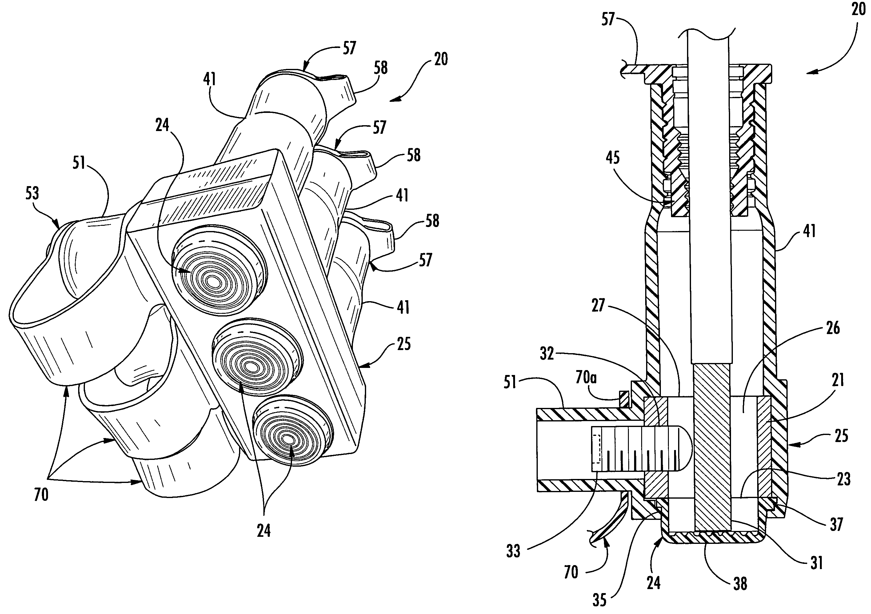
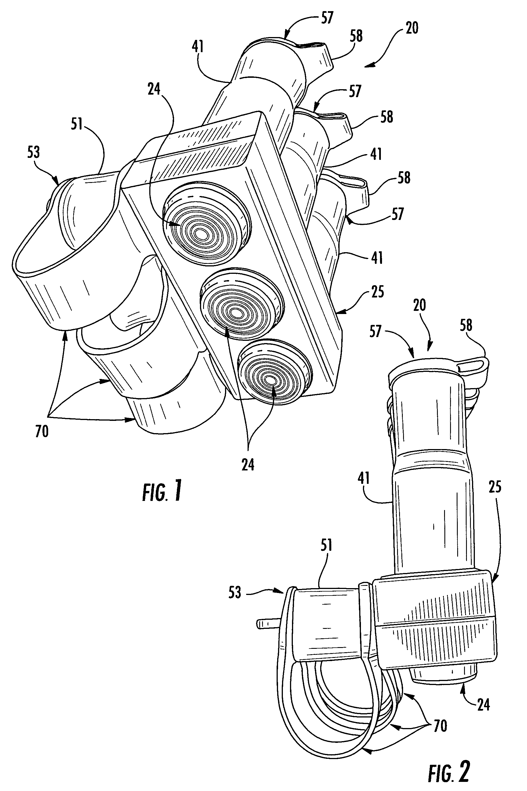
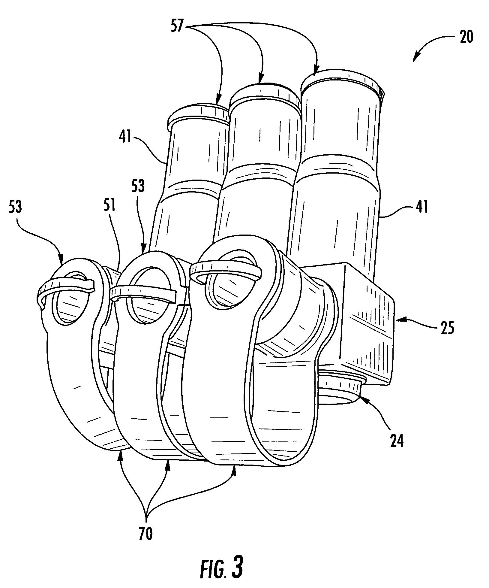
[0032]Referring now initially to FIGS. 1–7, an electrical connector 20 in accordance with the present invention is described. The electrical connector 20 is for a plurality of electrical cables and illustratively comprises an electrically conductive body 21 (FIG. 4), an insulating cover 25, and a plurality of windows 24 aligned with cable end viewing openings 23 (F...


PUM


Abstract

An electrical connector includes an electrically conductive body having spaced apart cable-receiving passageways for receiving respective electrical cable ends. The electrically conductive body may also have at least one respective fastener-receiving passageway intersecting each of the cable-receiving passageways. An insulating cover may be on the electrically conductive body and include an integrally molded respective tubular cable inlet aligned with each cable inlet opening. A respective insulating boot may be received in each of the tubular cable inlets. Each insulating boot may include a tubular sidewall having a progressively increasing diameter to an open outer end thereof, a removable boot closure cap for removable positioning in the open outer end of the tubular sidewall, and an integrally molded tether connecting the removable boot closure cap to the tubular sidewall.

Description

FIELD OF THE INVENTION[0001]The present invention relates to the field of electrical components, and, more particularly, to an electrical connector for connecting together a plurality of cable ends, and associated methods.BACKGROUND OF THE INVENTION[0002]Underground and submersible junction bus connectors are widely used in electrical power distribution systems. One type of such connector is offered under the designation SWEETHEART® by Homac Mfg. Company of Ormond Beach, Fla., the assignee of the present invention. The SWEETHEART® connector is a cast or welded aluminum connector including a bus, or bar, portion and a series of tubular posts extending outwardly from the bus portion. The posts have an open upper end to receive one or more electrical conductors. A threaded bore is provided in the sidewall of the post, and which receives a fastener to secure the electrical conductor within the upper end of the post. An insulating coating is provided on the lower portion of the posts and...

Claims


Application Information

Patent Timeline
Patent Type & Authority Patents(United States)
IPC IPC(8): H01R13/52
CPCH01R13/518H01R13/5213H01R13/5208
Inventor ZAHNEN, JAMES L.JAZOWSKI, ROY E.LUBINSKY, PAUL W.
Owner THOMAS & BETTS INT INC
Why Eureka
Try Eureka