Foil seal lamp

a seal lamp and oil-filled technology, applied in the direction of leading-in conductors, gas-filled discharge tubes, other chemical processes, etc., can solve the problems of crack formation in the seal area, glass does not flow according, and it is impossible to completely eliminate the cavity g, so as to achieve the effect of long service li

Active Publication Date: 2006-08-22
USHIO DENKI KK
View PDF20 Cites 2 Cited by
  • Summary
  • Abstract
  • Description
  • Claims
  • Application Information

AI Technical Summary

Benefits of technology

[0022]The invention was devised to fundamentally eliminate the above described disadvantages in the prior art. Thus, a first object of the invention is to devise a foil seal lamp in which, even when a high temperature of the seal area is reached, oxidation of the molybdenum metal foils and the molybdenum outer leads which have been installed in the seal area can be reliably prevented, and in which a long service life can be obtained.
[0023]A second object of the invention is to provide a foil seal lamp in which, using a material with an extremely small effect on the environment, oxidation of molybdenum metal foils and molybdenum outer leads which are installed in the seal area can be reliably prevented.
[0036]As a result, the metal foils of molybdenum and the outer leads of molybdenum are not oxidized even if a high temperature of the seal area of roughly 600° C. is reached. Thus, advantageously hermetic sealing is produced. This yields a foil seal lamp with a long service life in which the seal areas are not damaged even during operation in such an oxidized environment with a high temperature.
[0037]Furthermore, for the outer leads, since the surfaces of the areas which are installed in the seal areas are rough, the sealant for forming the protective coatings can be easily applied to the surfaces of the outer leads. Thus, an amount of the sealant for forming the protective coatings as large as possible is carried, by which the protective coatings of the crystalline molybdate become thick, and by which the heat resistant action and anti-oxidation effect are increased.
[0038]The protective coatings of crystalline molybdate are also formed in the areas which project from the seal areas of the outer leads. During operation the outer leads reach a high temperature of greater than or equal to 500° C. and are exposed to the outside air. The outer leads which project from the seal areas are oxidized, vaporized and finally become quite thin, by which the resistance value increases, and by which Joulean heat causes a still higher temperature. If, in this way, the outer leads reach a high temperature, the heat is transferred to the outer leads and the metal foils which are installed in the seal areas, by which a state is obtained in which oxidation easily occurs. By the formation of the protective coatings in the areas which project from the seal areas of the outer leads, the areas which project from the seal areas of the outer leads are not oxidized and do not become thin either. The temperature of the outer leads in the areas which project from the seal areas therefore does not rise. The temperature of the outer leads and the metal foils which are installed in the seal areas does not rise. As a result, oxidation is prevented and damage to the seal area can be reliably prevented. Thus, a foil seal lamp with a longer service life can be obtained.
[0039]Furthermore, for the outer leads, since at least the surfaces of the areas which project from the seal areas are rough, the sealant for forming the protective coatings can be easily applied to the surfaces of the outer leads which project from these seal areas. Thus, an amount of the sealant for forming the protective coatings as large as possible is carried, by which protective coatings of the crystalline molybdate become thick, and by which the heat-resistant action and anti-oxidation action of the outer leads are increased.

Problems solved by technology

A relatively large outer lead, however, is not entirely located directly tightly adjoining the glass because, as a result of the high viscosity of the glass, the glass does not flow adequately according to the shape of the outer lead, and because the difference between the coefficients of thermal expansion between the outer lead and the glass is large.
Therefore, it is impossible, in fact, to completely eliminate the cavity G.
This leads to crack formation in the seal areas.
Therefore, this has resulted in cases in which the lamp was ultimately destroyed.
Therefore, the above described disadvantage has also occurred here.
However, there was the disadvantage of a reduction of the strength of adhesion to the glass.
In this process, there is the disadvantage of high production costs because coating is done beforehand, prior to sealing.
In such a process in which the metal foil and the outer lead are coated with chromium, there are the disadvantages of complicated production processes and high production costs because sealing takes place after coating of the metal foil and the outer lead with chromium.
Furthermore, recently, environmental concerns have become more critical.
There is the tendency for material with high environmental burden to be limited, chromium not constituting an exception either.
The mist which is formed by the electrolytic bath in the galvanization process and which contains hexavalent chromium is said, however, to cause lung cancer.
This means that the environmental effect in the production process is regarded as a problem.
Furthermore, a chromium coating which decomposes in chromous acid and chromium chloride, as was described in U.S. Pat. No. 3,420,944, due to production of hexavalent chromium is inherently environmentally harmful and therefore disadvantageous.
But since Tl2O3 is used, the effect on the environment is considered disadvantageous.
However, since lead oxide is used, the effect on the environment is regarded as more and more disadvantageous.
Even when these tests were carried out, in an environment with a temperature of the seal area of greater than 400° C., oxidation of the metal foil of molybdenum and of the outer lead of molybdenum which are exposed to the cavity of the seal area could not be reliably prevented.
Furthermore, there was the disadvantage that to prevent oxidation a substance must be used which has an adverse effect on the environment.

Method used


Image

  • Foil seal lamp
  • Foil seal lamp
  • Foil seal lamp

Examples


embodiments

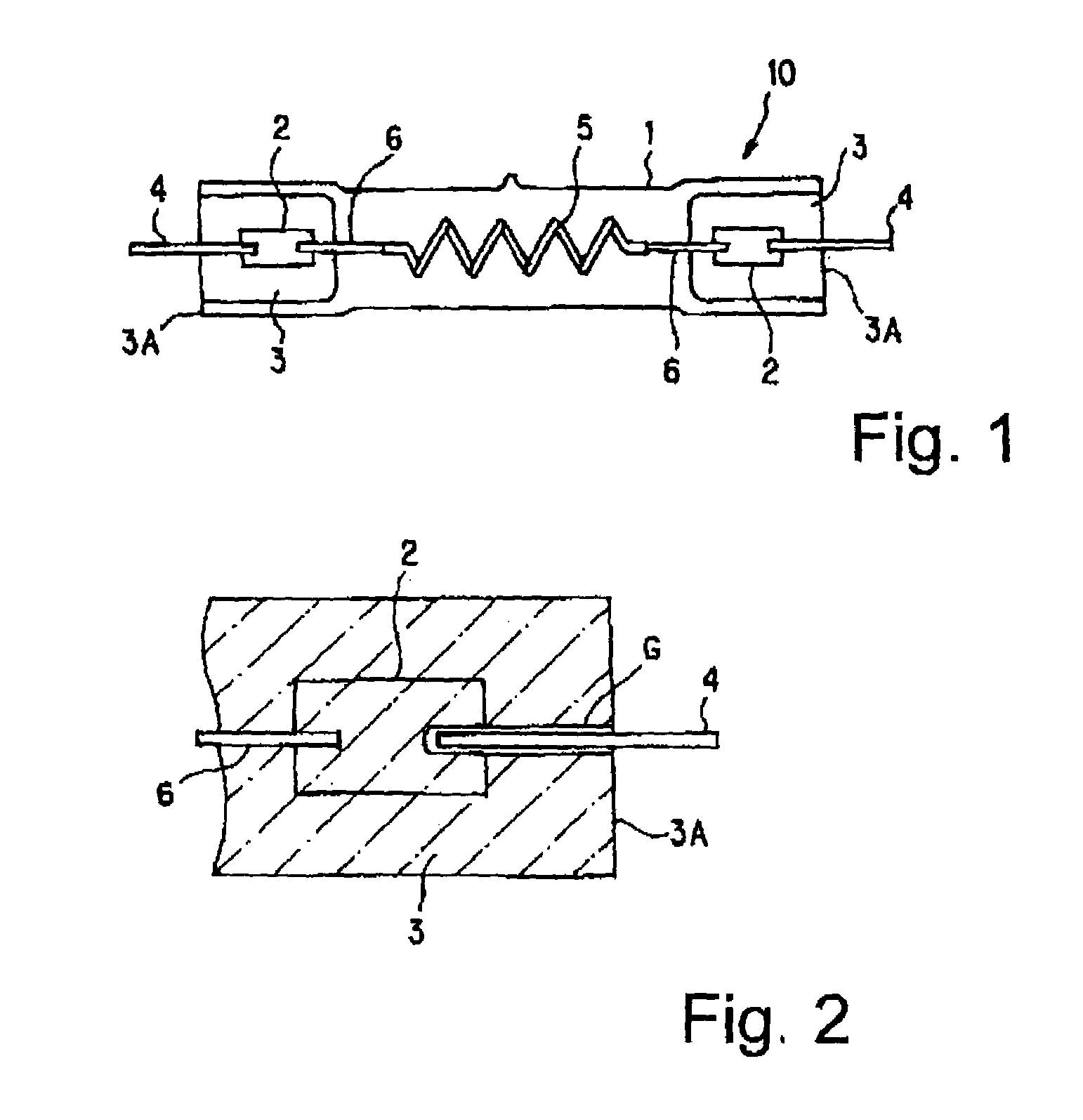
[0117]The outer shape of the foil seal lamp is identical to that of the filament lamp described in the prior art. The feature of the invention is described using FIG. 9.

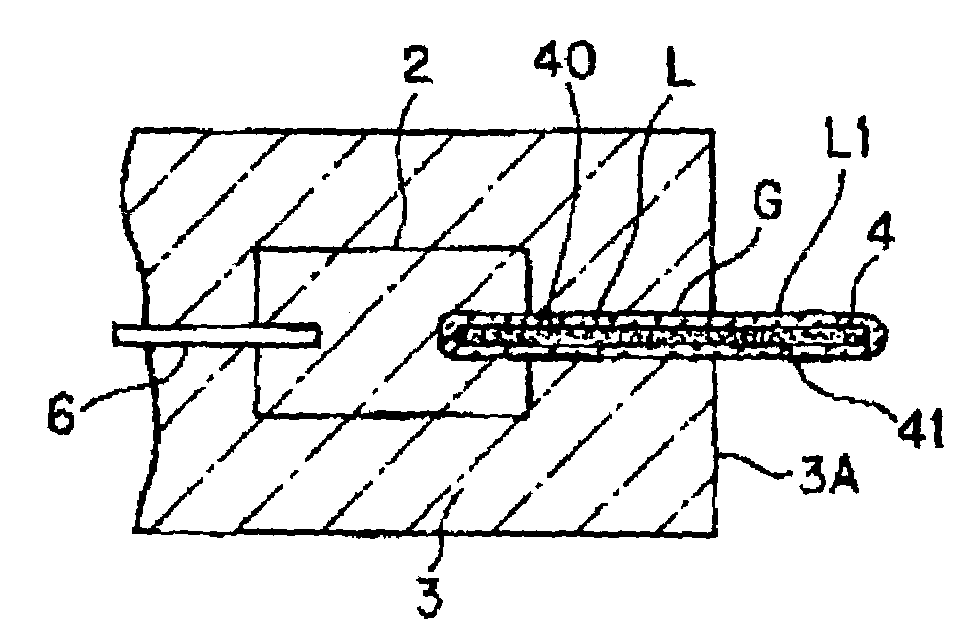
[0118]As is shown in FIG. 9, in the vicinity of the molybdenum outer lead 4, there is an extremely small cavity G which extends from the outer end face 3A of the seal area 3 to the molybdenum metal foil 2. The outer lead 4 projects from the seal area 3 to the outside.

[0119]If a sealant L (also called a “sealant for forming a protective coating L”) which is formed of an aqueous solution of a nitrate with element / elements chosen from one or more of the elements magnesium, calcium, strontium, barium, manganese, cobalt, nickel, titanium, scandium, yttrium, lanthanum, cerium, praseodymium, neodymium, samarium, europium, gadolinium, terbium, dysprosium, holmium, erbium, thulium, ytterbium, and lutetium is allowed to drip in a suitable amount by a suitable injection means into the outer periphery of the outer lead 4 on the ...

experimental example 1

[0133]An embodiment of the invention is described below.

[0134]A tungsten-halogen lamp of the double end type is produced in which there are seal areas on both sides of a silica glass bulb, as is shown in FIG. 1.

[0135]In the example which is shown in FIG. 9 and which corresponds to claim 1, an aqueous Mn(NO3)2 solution, as the sealant for forming the protective coatings, was allowed to drip into the cavity which is present on the outer end face of the seal area. The sealant for forming the protective coatings penetrated the cavity between the silica glass and the molybdenum outer lead and traveled to the outer end of the molybdenum metal foil.

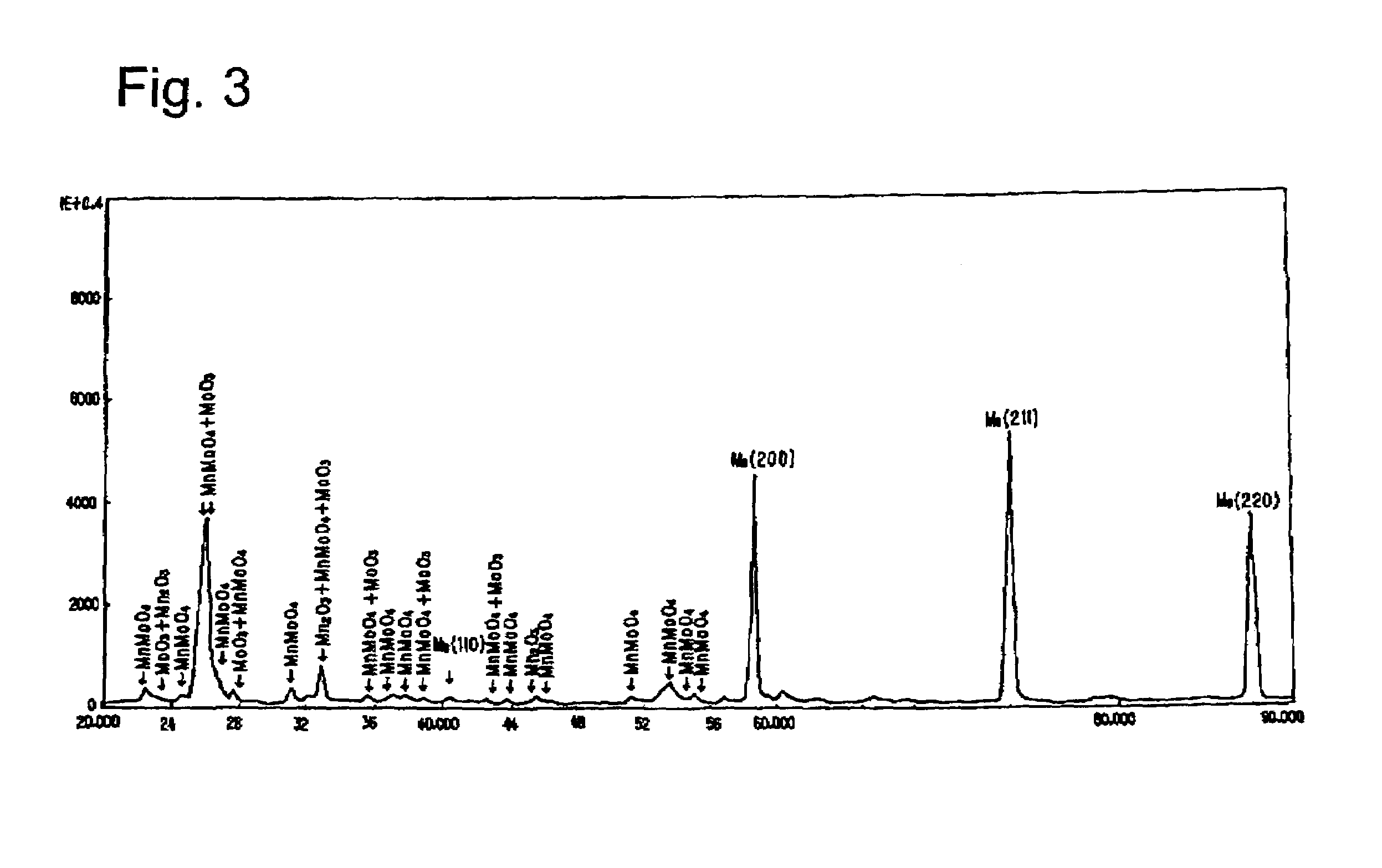
[0136]It appears that this sealant for forming the protective coatings fills the cavity and that the metal foil and the outer lead becomes wet. Such a lamp is placed in a drying furnace and dried. The lamp, after drying in an electric furnace, was heat treated to form a protective coating of crystalline molybdate on the surfaces of the molybdenu...


PUM

PropertyMeasurementUnit
surface roughnessaaaaaaaaaa
temperatureaaaaaaaaaa

Abstract

A foil seal lamp in which even when a high temperature of the seal area is reached oxidation of the molybdenum metal foils and the molybdenum outer leads which have been placed in the seal area can be reliably prevented, and in which a long service life can be obtained. is achieved by providing the surfaces of the metal foil and the outer lead which are placed in the seal areas with protective coatings of crystalline molybdate. An increase in the amount of protective coating that can be carried is produced by surface roughening the outer leads.

Description

BACKGROUND OF THE INVENTION[0001]1. Field of the Invention[0002]The invention relates to a foil seal lamp in which in the seal area a metal foil of molybdenum and an outer lead of molybdenum are installed.[0003]2. Description of Related Art[0004]A conventionally known foil seal lamp is described below. FIG. 1 shows a foil seal lamp of the filament lamp type with bilateral seal areas. FIG. 2 shows the seal area of the foil seal lamp as shown in FIG. 1 in an enlargement.[0005]In the figure, a filament lamp 10 has seal areas 3 which are formed on the two ends of a glass bulb 1, and in each of which a metal foil 2 of molybdenum is installed. An outer lead 4 of molybdenum is connected to one end of the respective metal foil 2 by welding and projects from the outer end face 3A of the respective seal area 3 to the outside. On the other hand, within the bulb 1 there is a filament 5. The two ends of the filament 5 are welded via inner leads 6 to the metal foils 2 which are located on the two...

Claims


Application Information

Patent Timeline
Patent Type & Authority Patents(United States)
IPC IPC(8): H01J17/18C04B103/61H01J61/36H01K1/38H01K1/40
CPCH01K1/38H01J61/368
Inventor KAI, KENZONAKAMURA, KAORUMORIKAWA, KAZUNORI
Owner USHIO DENKI KK
Why Eureka
Try Eureka