NMR probe for material analysis

a technology of nmr-mouse probe and material analysis, which is applied in the direction of geological measurements, analysis using nuclear magnetic resonance, reradiation, etc., can solve the problems of insufficient signal-to-noise ratio and unsatisfactory yield of measuring signals from volume area excited by nmr-mouse prob

Inactive Publication Date: 2006-08-22
PROF DR BERNHARD
View PDF5 Cites 20 Cited by
  • Summary
  • Abstract
  • Description
  • Claims
  • Application Information

AI Technical Summary

Benefits of technology

[0013]It is expedient if the current conductors are disposed in, or on, a separate carrier structure which can be connected to the magnet which generates the polarization field B0. As carrier material, an electrically non-conductive material is used, particularly silicon, glass or a ceramic material. The carrier structure may consist of a material which is particularly selected for the examinations to be performed by the NMR probe. In order to avoid wetting, the carrier surface may be hydrophobic. In order to be able to mount the carrier onto the polarization magnet in a simple manner a support is provided for the carrier by which the carrier can be fixed by magnetic forces. The support preferably consists of a steel sheet.

Problems solved by technology

In connection with the present NMR-MOUSE apparatus, it is however disadvantageous that the given inhomogeneities of the permanent magnetic polarization field B0 and the excitation field B1 result in a dissatisfactory yield of the measuring signals from the volume area excited by an NMR-MOUSE probe by means of the radio frequency circuit.
The signal to noise ratio is insufficient for demanding requirements particularly if thin material layers have to be examined.

Method used


Image

  • NMR probe for material analysis
  • NMR probe for material analysis
  • NMR probe for material analysis

Examples


Embodiment Construction

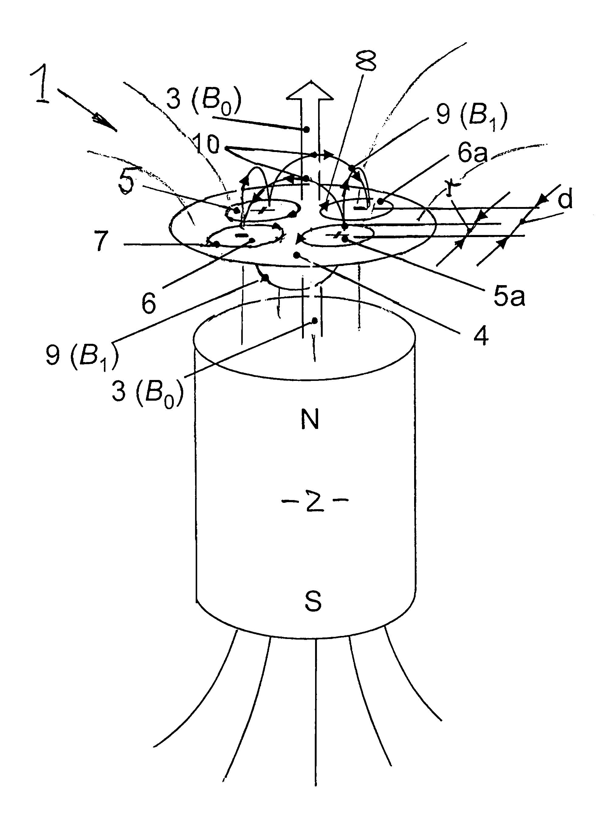
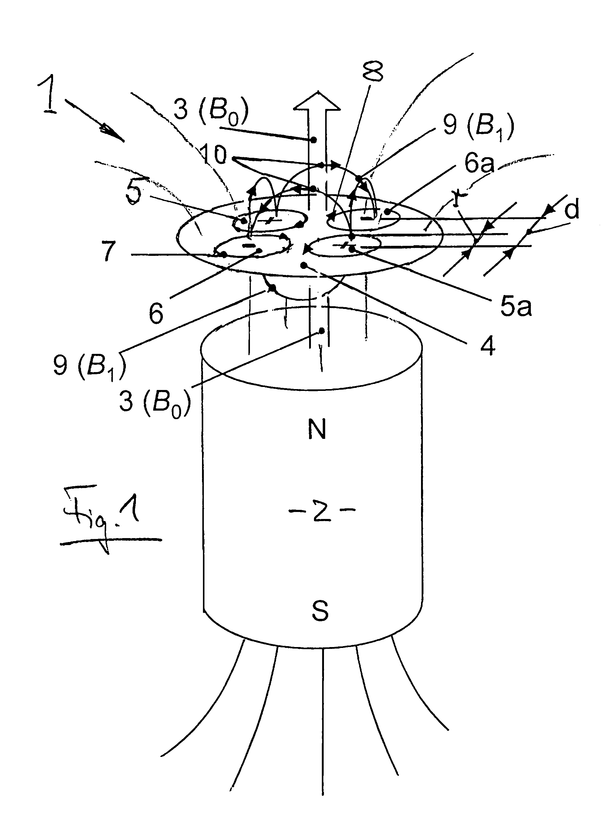
[0028]In FIG. 1, the principle on which the invention is based is explained on the basis of a particular embodiment. FIG. 1 shows schematically an NMR probe 1, for example of the type NMR-MOUSE, in a static polarization field B0, which is generated by a permanent magnet 2 with a magnetic north (N) and south (S) pole, and the magnetic field lines 3 thereof, with several radio frequency coils (RF-coils) 5, 5a, 6, 6a being arranged in a plane extending normal to the polarization field B0. Upon use of the NMR-probe for material analysis the polarization field B0 serves for the polarization of the nuclear spins in the material which is to be examined; and the RF coil for the generation of pulsed magnetic excitation field B1, which is super-imposed on the highly inhomogeneous time-constant permanent magnetic polarization field B0 for the excitation of nuclear spin echoes (S). The obtained nuclear spin echoes are the characteristic values for the material to be examined by the NMR probe in...


PUM

PropertyMeasurementUnit
distanceaaaaaaaaaa
distancesaaaaaaaaaa
distancesaaaaaaaaaa

Abstract

In a unilateral NMR probe for the analysis of a material comprising at least one magnet for generating a constant time-invariant polarization field B0 in the material to be analyzed and current conductors forming a radio frequency oscillation circuit for generating a pulsed radio frequency magnetic excitation field B1 which is superimposed on the polarization field N0 in the material, the circuit conductors are so designed as to provide several adjacent excitation fields B0 with alternatingly oppositely oriented magnetic fields, whereby the current conductors generating each one of the excitation fields have a distance from each other which causes a certain penetration depth in the material to be analyzed and echoes received therefrom provide measurement values which are characteristic for the material being analyzed.

Description

[0001]This is a Continuation-In-Part Application of international application PCT / EP03 / 03823 filed Apr. 12, 2003, and claiming the priority of German application 102 16 387.4 filed Apr. 14, 2002.BACKGROUND OF THE INVENTION[0002]The invention relates to an NMR probe for the analysis of materials by nuclear magnetic resonance. The probe comprises a magnet, for example an electromagnet or a permanent magnet for generating a constant time-invariant polarization field Bo in the material to be examined and a radio frequency oscillation circuit for generating a pulsed high-frequency magnetic excitation field B1, which is superimposed on the polarization field Bo to generate echo signals S in the material which are determined by the NMR probe as material-characteristic measurement values. The echo signals can be measured on a time basis after changes of the magnetic field by way of two or more radio frequency pulses provided by the NMR probe, the third and subsequent pulses after an echo pe...

Claims


Application Information

Patent Timeline
Patent Type & Authority Patents(United States)
IPC IPC(8): G01V3/00G01N24/08G01R33/341G01R33/38
CPCG01R33/3808G01R33/341G01N24/08G01R33/383
Inventor BLUMICH, BERNHARDBRUDER, MICHAELKLEIN, MARTINKRAUSE, KARL-HEINZRABKIN, MICHAELSTANGENBERG, JURGENANFEROV, VLADIMIRANFEROVA, SOPHIAFECHETE, RADU
Owner PROF DR BERNHARD
Why Eureka
Try Eureka