Image processing apparatus and method

Active Publication Date: 2006-08-22
KK TOSHIBA
View PDF8 Cites 138 Cited by
  • Summary
  • Abstract
  • Description
  • Claims
  • Application Information

AI Technical Summary

Benefits of technology

[0013]It is an object of the present invention to provide image processing apparatus and method for sta

Problems solved by technology

However, it is difficult to set the threshold to the most suitable value irrespective of weather condition or illumination condition.
Accordingly, processing to set the search area is often complicated in the prior art.
However, processing to set the direction of the white line candidate is often complicated because the slope of the white line on the camera image is changed by the vehicle's location.
Additionally, the processing is complicated by selection of the suitable

Method used


Image

  • Image processing apparatus and method
  • Image processing apparatus and method
  • Image processing apparatus and method

Examples


Embodiment Construction

[0034]Various embodiments of the present invention will be explained by referring to the drawings.

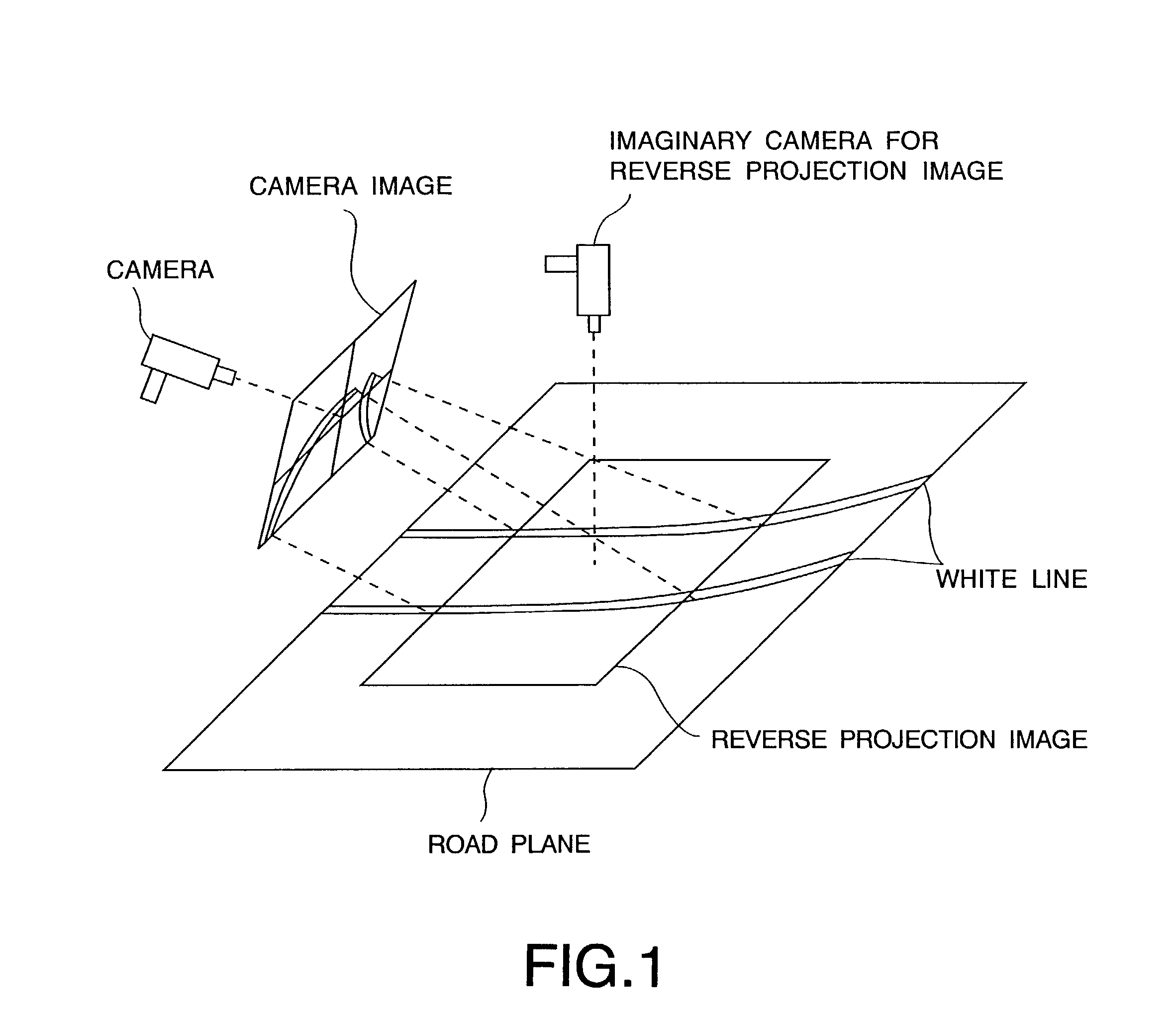
[0035]In embodiments of the present invention, first, a plurality of images is input in a time series by photographing a scene, such as a road surface in advance of a vehicle. In general, the time series image is projected onto an imaginary plane corresponding to the road plane (hereinafter, this imaginary plane is called a plane), and a projection image is generated upon which information related to or representing the time series image is projected. Last, a boundary line is detected from the projection image.

[0036]In the image processing apparatus of the present invention, “a plane” represents the road plane (or more generally the road surface) and “a boundary line” represents a high contrast line, such as the white line or the shoulder of a road as a traveling lane. However, in case that the environment is indoors, the plane can represent a face, such as a floor or a passage, and the...


PUM


Abstract

An image input unit inputs a plurality of images in a time series. Each input image includes a boundary line extending toward a vanishing point on a plane. A reverse projection image generation unit generates a reverse projection image of each input image by projecting information related to each input image onto the plane. A boundary line detection unit detects the boundary line from the reverse projection image by identifying a boundary line candidate on each reverse projection image.

Description

CROSS-REFERENCE TO RELATED APPLICATIONS[0001]This application is based upon and claims the benefit of priority from the prior Japanese Patent Application PH2001-218812, filed on Jul. 18, 2001, the entire contents of which are incorporated herein by reference.FIELD OF THE INVENTION[0002]The present invention relates to image processing apparatus and method for stably detecting a boundary line existing on a lane from time series images input through TV camera or video camera.BACKGROUND OF THE INVENTION[0003]In the prior art, as a method for detecting a boundary line (white line) on a plane (road plane) from time series images input from a camera loaded on a vehicle, various kinds of image processing techniques are known.[0004]As one method of a preprocessing method, the gradient of intensity values between the white line and the road plane is aimed. In this method, the edge intensity is binalized on a camera image (input image), and a white line candidate is restricted. For example, a...

Claims


Application Information

Patent Timeline
IPC IPC(8): H04N7/18G06T1/00G06T5/00G06T7/60G08G1/16
CPCG06T7/0083G06T2207/30256G06T2207/10016G06T7/12
Inventor NAKAYAMA, HIROMITSUKUBOTA, SUSUMUTANIGUCHI, YASUHIRO
Owner KK TOSHIBA
Why Eureka
Try Eureka