
Liquid crystal display device comprising a pad in contact with a light guide and maintaining a distance between a panel guide and a backlight assembly

a technology of liquid crystal display and light guide, which is applied in the direction of identification means, lighting and heating apparatus, instruments, etc., to achieve the effect of constant distan

Inactive Publication Date: 2006-08-22
LG DISPLAY CO LTD
View PDF6 Cites 27 Cited by
  • Summary
  • Abstract
  • Description
  • Claims
  • Application Information

AI Technical Summary

Benefits of technology

[0008]An object of the present invention is to provide a liquid crystal display that is capable of preventing optical sheets from being damaged or wrinkled by a panel guide.
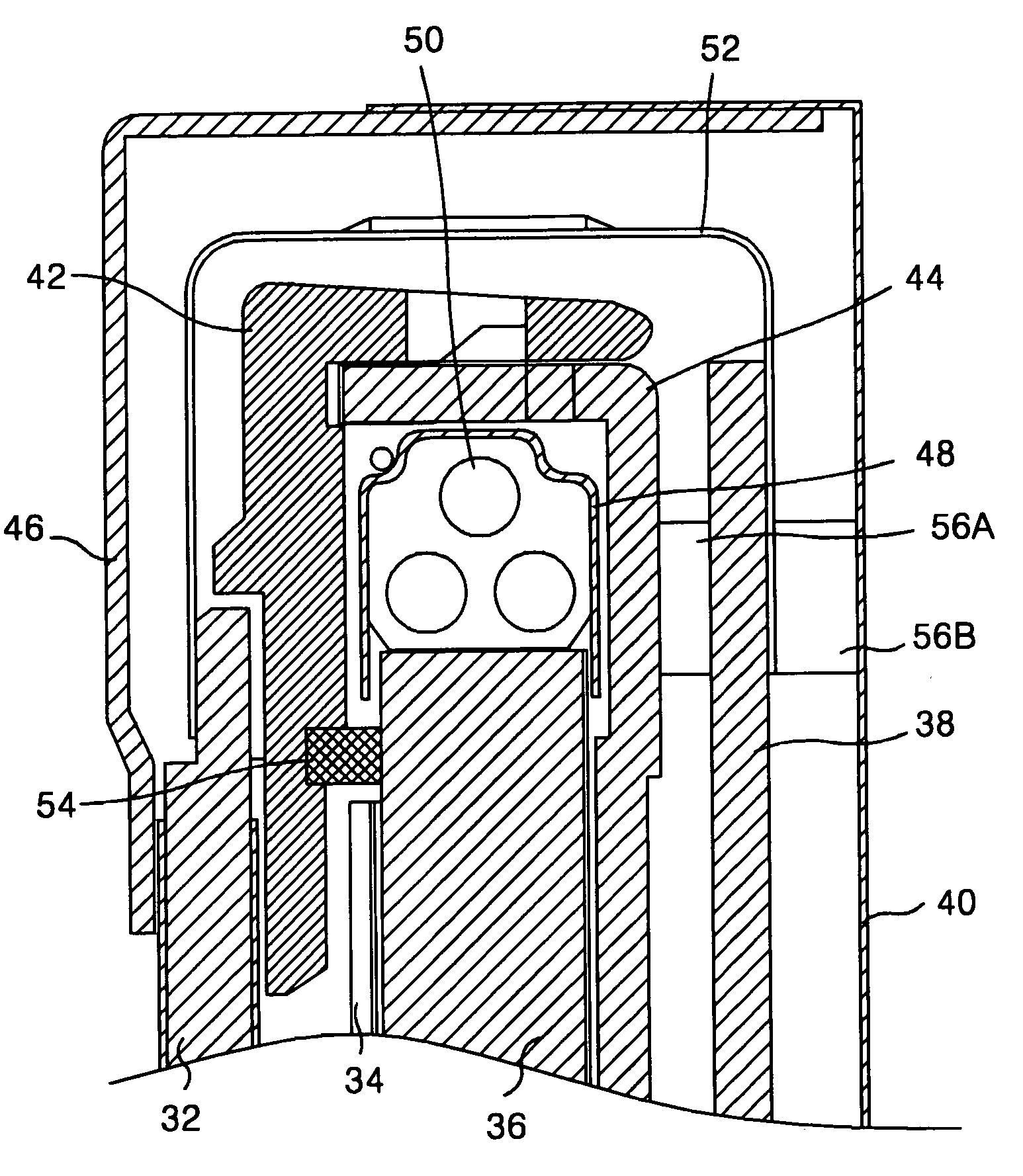
[0010]To achieve these and other advantages and in accordance with the purpose of the present invention, as embodied and broadly described, a liquid crystal display device according to the present invention includes a liquid crystal panel; a backlight assembly for radiating light onto the liquid crystal panel; a panel guide provided between the backlight assembly and the liquid crystal panel to support the liquid crystal panel; and a pad or insulator provided between the panel guide and the backlight assembly to maintain a constant distance between the panel guide and the backlight assembly and to shut off heat and to prevent a foreign substance from flowing into the liquid crystal panel.

Problems solved by technology

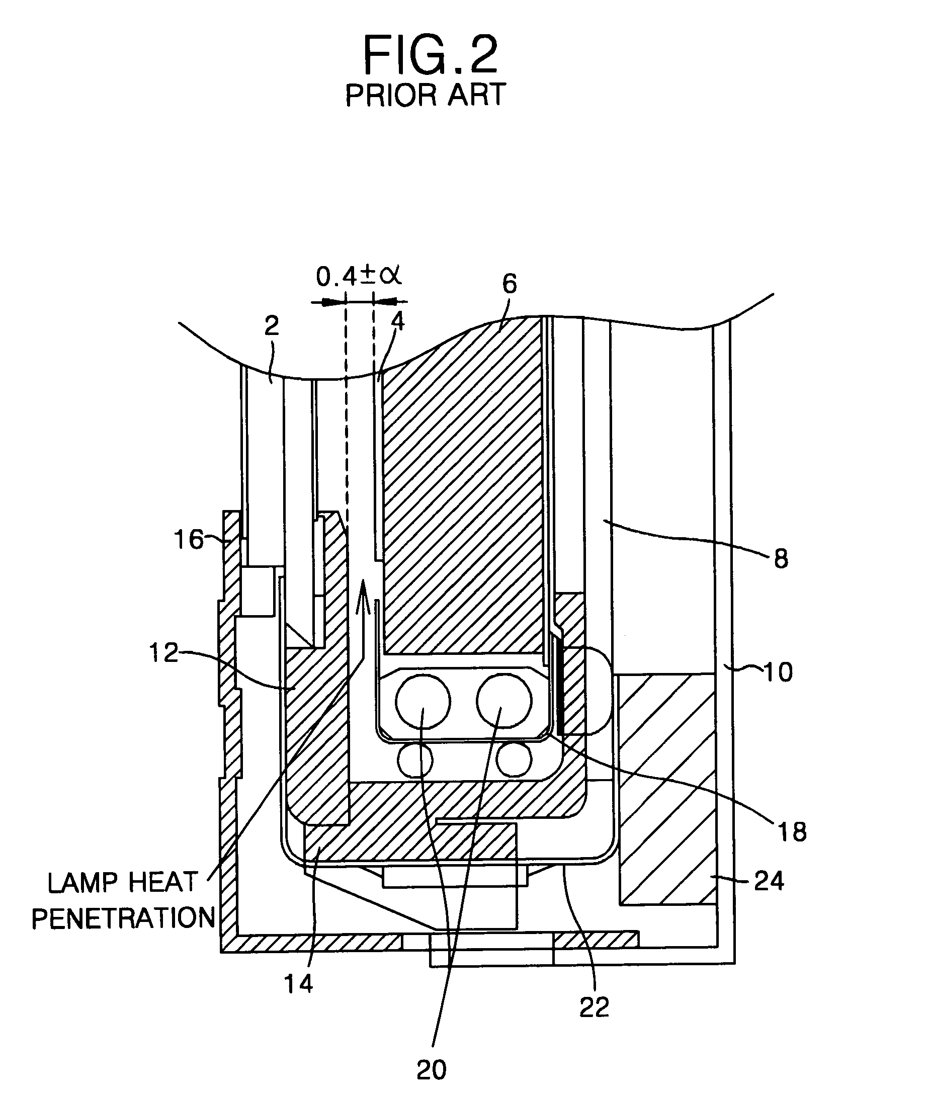
This causes the problem that the panel guide 12 is pressed down by a load of the liquid crystal panel 2 itself or a pressure generated upon assembly, etc. to pressurize the optical sheet 4 in the conventional liquid crystal module.
Furthermore, the conventional liquid crystal module has a problem in that a short between the pads or the patterns is generated by a foreign substance flowing into the liquid crystal panel 2, the PCB 8 and the TCP 22 via the gap upon change of the backlight assembly or in an assembly process of the liquid crystal module.

Method used


Image

  • Liquid crystal display device comprising a pad in contact with a light guide and maintaining a distance between a panel guide and a backlight assembly
  • Liquid crystal display device comprising a pad in contact with a light guide and maintaining a distance between a panel guide and a backlight assembly
  • Liquid crystal display device comprising a pad in contact with a light guide and maintaining a distance between a panel guide and a backlight assembly

Examples


Embodiment Construction

[0019]Reference will now be made in detail to the preferred embodiment of the present invention, example of which is illustrated in the accompanying drawings.

[0020]Referring to FIG. 4 and FIG. 5, there is shown a liquid crystal display (LCD) according to a first embodiment of the present invention. The LCD includes a first silicon pad 54 provided between a backlight assembly and a panel guide 42, a second silicon pad 56A provided between a main frame 44 and a printed circuit board (PCB) 38, and a third silicon pad 56B provided between the PCB 38 and the bottom case 40. The backlight assembly has a lamp 50, a lamp housing 48, a light guide 36 and optical sheets 34, and is received within the main frame 44 to be secured by the main frame 44. The first silicon pad 54 is substantially made from an elastic silicon, and is provided between the light guide 36 and the panel guide 42 to support the panel guide 42. The first silicon pad 54 maintains a constant gap between the optical sheet 34...


PUM

PropertyMeasurementUnit
distanceaaaaaaaaaa
thicknessaaaaaaaaaa
distanceaaaaaaaaaa

Abstract

A liquid crystal display device that can prevent optical sheets from being damaged and wrinkled by a panel guide. In the device, a backlight assembly radiates a light onto the liquid crystal panel. A panel guide is provided between the backlight assembly and the liquid crystal panel to support the liquid crystal panel. A pad is provided between the panel guide and the backlight assembly to maintain a distance between the panel guide and the backlight assembly and to shut off a heat and a foreign substance flowing into the liquid crystal panel.

Description

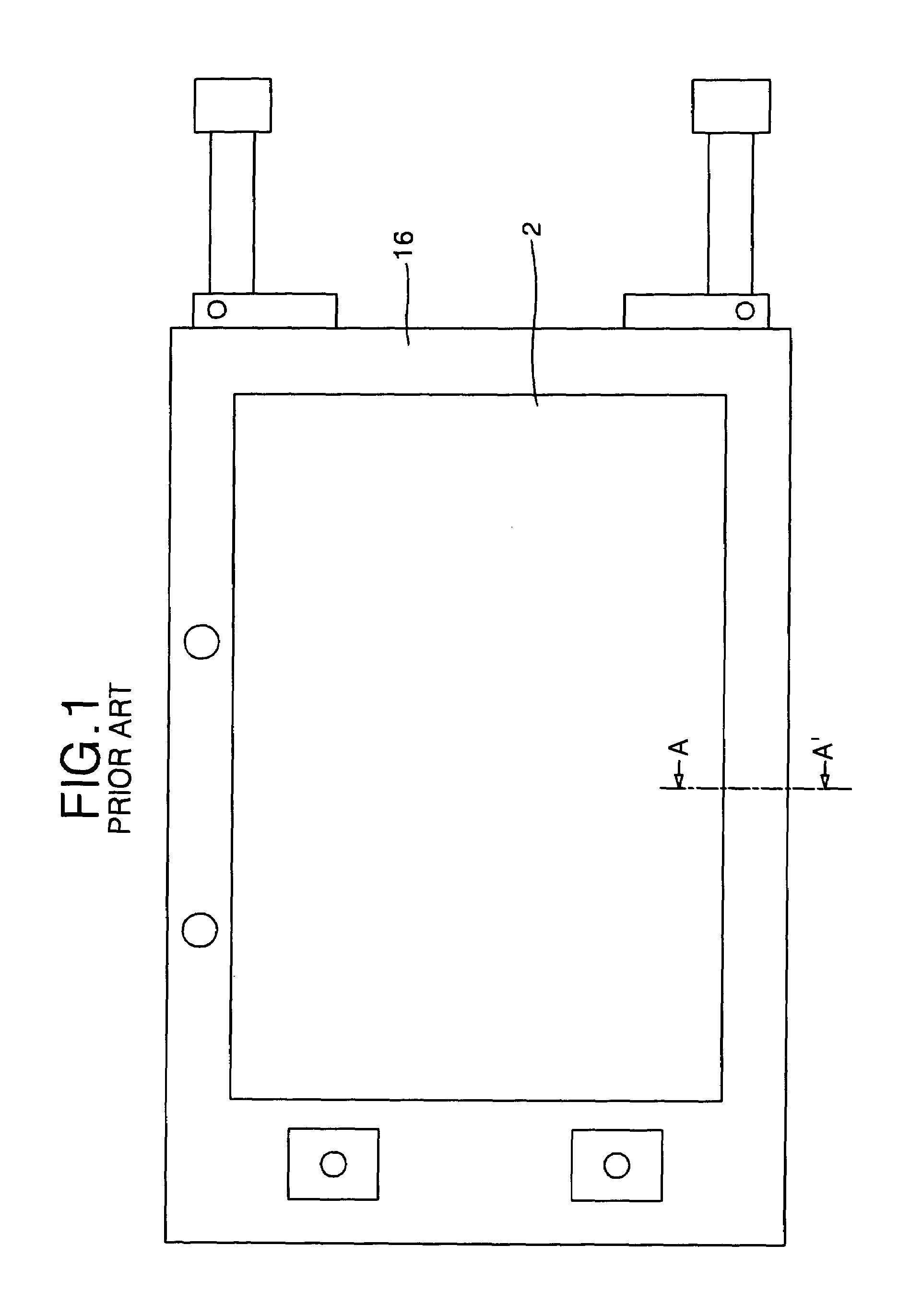
[0001]This application claims the benefit of Korean Patent Application No. 2000-48433, filed on Aug. 21, 2000, which is hereby incorporated by reference.BACKGROUND OF THE INVENTION[0002]1. Field of the Invention[0003]The present invention relates to a liquid crystal display, and more particularly to a liquid crystal display that is capable of preventing optical sheets from being damaged and wrinkled by a panel guide.[0004]2. Discussion of the Related Art[0005]Generally, as shown in FIG. 1 and FIG. 2, a liquid crystal module used as a display device in a notebook computer includes a main frame 14 received with a backlight assembly, a panel guide 12 attached to the upper portion of the main frame 14 in parallel, a liquid crystal panel 2 loaded onto the panel guide 12, a top case 16 for surrounding the edge of the liquid crystal panel 2 and the side of the main frame 14, and a bottom case 10 contacting the side of the top case 16 to surround the bottom of the liquid crystal module. As ...

Claims


Application Information

Patent Timeline
Patent Type & Authority Patents(United States)
IPC IPC(8): G02F1/1333G02F1/13G02F1/133G02F1/13357G09F9/00
CPCG02F1/133308G02F2001/133311G02F1/133615G02F1/133311G02F1/133
Inventor KIM, KYOUNG SUB
Owner LG DISPLAY CO LTD
Learn More