
Code puncturing method and apparatus

a puncturing method and code technology, applied in the field of code puncturing methods and apparatuses, can solve problems such as multipath interference, errors, and transmission signals that are corrupted in many ways

Inactive Publication Date: 2006-08-22
AVAGO TECH WIRELESS IP SINGAPORE PTE
View PDF12 Cites 29 Cited by
  • Summary
  • Abstract
  • Description
  • Claims
  • Application Information

AI Technical Summary

Problems solved by technology

Errors occur due to interference and channel limitations which distort the data.
Transmitted signals are corrupted in many ways before reaching the intended receiver.
Interference from signals sent by other transmission sources, leakage from power lines and wired communication systems and the like will all act to corrupt a desired signal.
This latter portion of the signal reaches the receiver at a later time than the first portion of the signal, causing a type of interference known as multipath.
These interference sources, and others, make it very difficult for a receiver to receive a transmitted signal with an acceptable degree of accuracy, and will increase the frequency of errors.
If the symbol 1 is sent and interference corrupts it such that it looks to the receiver like a 0, an error has occurred.
The disadvantage of such a system is the rate of information moving from transmitter to receiver is cut by ⅓ since every bit sent to the receiver requires the transmission of three chips.
In situations where the interference is relatively low, this 3:1 redundancy becomes an unnecessary waste of transmission bandwidth.
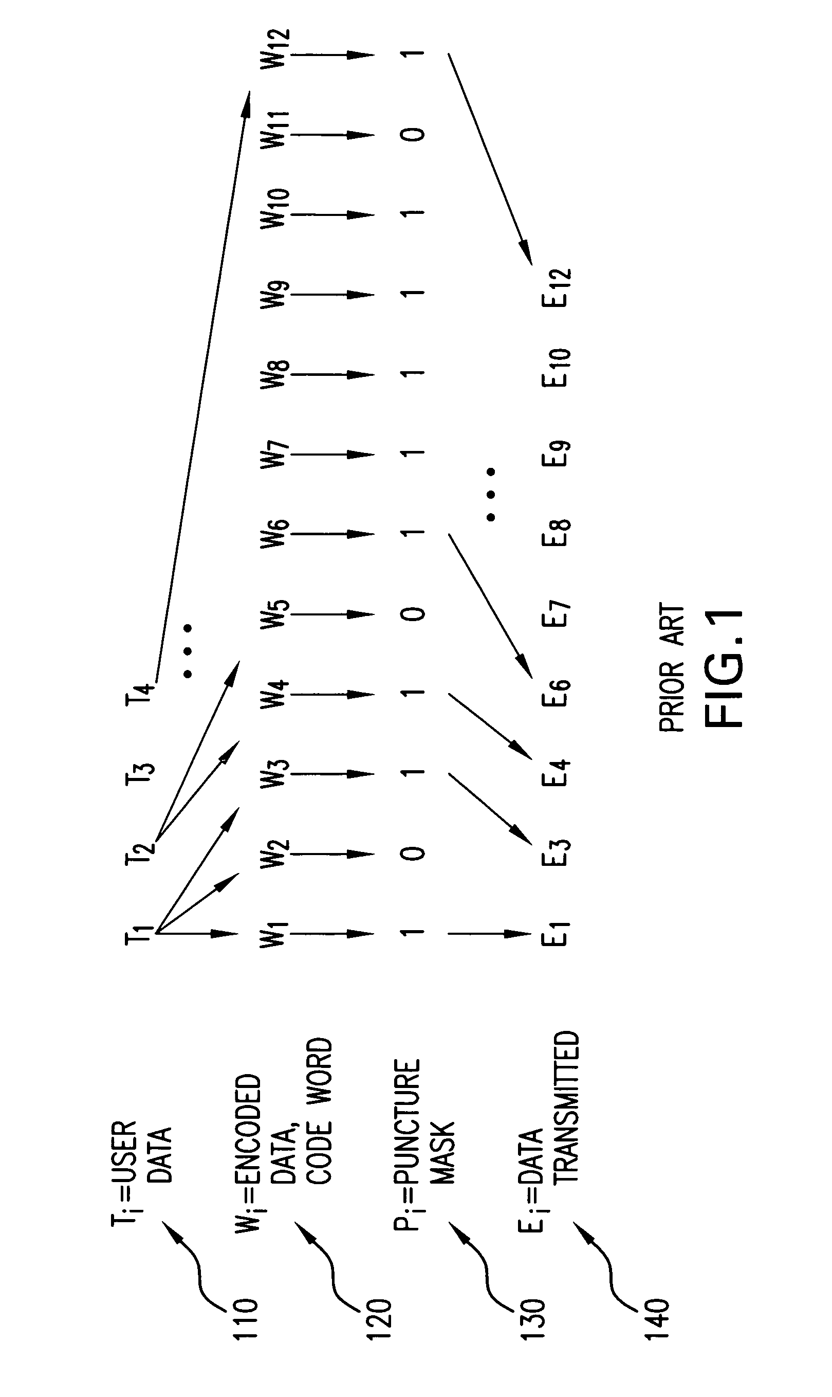
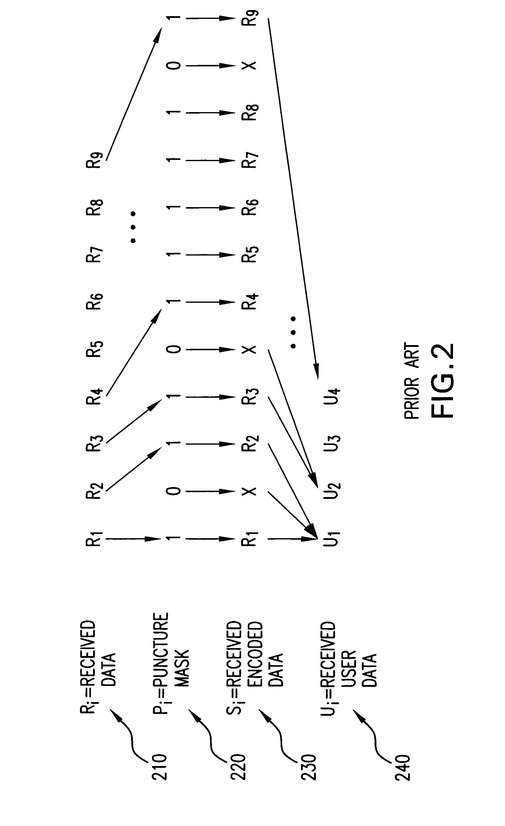
However, simply storing the puncture masks leads to a requirement of a fairly large memory on a VLSI chip designed to implement these wireless standards.

Method used


Image

  • Code puncturing method and apparatus
  • Code puncturing method and apparatus
  • Code puncturing method and apparatus

Examples


Embodiment Construction

[0027]Embodiments of the present invention use compression and decompression to reduce the memory required in electronic systems or on integrated circuits for storing a plurality of puncture masks.

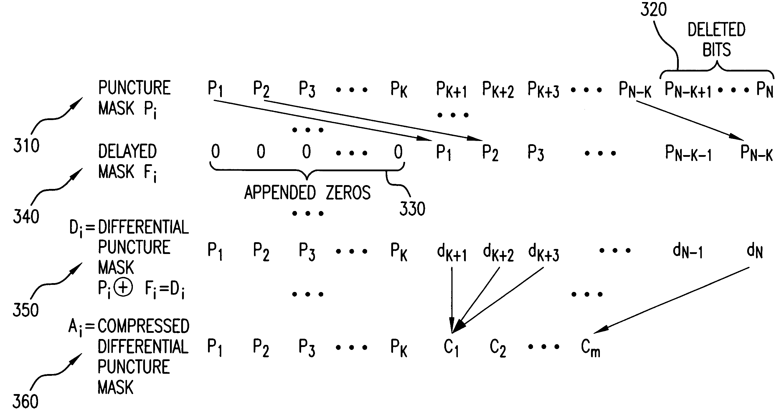
[0028]FIG. 3 shows one such method of compressing and decompressing a puncture mask. A puncture mask Pi 302 having a length, or number of bits n, is provided. The bits comprising the puncture mask Pi 302 are then compressed into a series of codes Ci 304. This compression may be done by one run length compression, zero run length compression, or any other suitable compression scheme. In one run length compression, starting with the first bit of the puncture mask Pi 302, the number of consecutive ones in a series in the puncture mask 302 is counted until a zero is reached. The number of ones that was counted is then stored as a binary word. This process is continued with the next bit following the zero until bit n of the puncture mask Pi 302 is reached. Zero run length coding works in a simi...


PUM


Abstract

A method of compressing a puncture mask information is disclosed, the method comprising making a delayed puncture mask by deleting the last k bits of the puncture mask; and appending k zeros to the beginning of the puncture mask; making a differential puncture mask by XORing the delayed puncture mask with the puncture mask; and compressing the differential puncture mask.

Description

[0001]The present invention relates to methods and apparatus for compressing and decompressing puncture masks for use in wireless communication systems.BACKGROUND OF THE INVENTION[0002]A goal in communication systems is to transmit and receive signals while utilizing minimal transmission channel bandwidth and keeping the overall error rate below an acceptable threshold. Channel bandwidth is filled by transmitters attempting to send ever more data. Errors occur due to interference and channel limitations which distort the data. Systems transmitting and receiving data include cell phones, personal digital assistants (PDAs), local area networks (LANs), wide area networks (WANs), and the like. Such systems may communicate unit to unit, such as cell phone to cell phone, or may use base stations, dish antennas, satellites, and the like.[0003]Transmitted signals are corrupted in many ways before reaching the intended receiver. Interference from signals sent by other transmission sources, l...

Claims


Application Information

Patent Timeline
Patent Type & Authority Patents(United States)
IPC IPC(8): H04B1/66
CPCH03M7/30H03M13/6362H03M13/6312H03M7/46
Inventor SHOHARA, AKI
Owner AVAGO TECH WIRELESS IP SINGAPORE PTE
Learn More