Wire end insert tool with replaceable cutting blade

a technology of wire end inserting and cutting blades, which is applied in the direction of manufacturing tools, other manufacturing equipment/tools, and unstripped conductor connection devices, etc., can solve the problems of circuit board damage, tool bodies used in impact type tool systems that have to be discarded, etc., and achieves cleaner cutting action, sharper and cleaner cutting, and reduces the force required to cut insulated wires

Active Publication Date: 2006-08-29
SULLSTAR TECH
View PDF15 Cites 16 Cited by
  • Summary
  • Abstract
  • Description
  • Claims
  • Application Information

AI Technical Summary

Benefits of technology

[0010]According to another alternate form of my invention a longitudinally extending stiffening rib is formed on the upper surface of the blade, to add to its stiffness and hence precision in cutting action.
[0012]In yet another alternate form of my invention the cutting end of the cutting blade is sharpened from both its lateral side edges, thus making for a cleaner cutting action.
[0013]An advantage of my invention is that the cutting blade may be replaced without having to replace the tool body with which the blade is used. A technician working in the field can carry smaller replacement blades in place of the larger and heavier tool bodies, and does not have to carry complete replacement tools. The smaller blades can be made readily available, which results in a considerable saving.
[0014]A further advantage is that in my invention the replaceable cutting blade is made from a material that is able to provide a sharper cutting edge, and therefore achieves a sharper and cleaner cut on the end of the insulated wire being terminated. This cutting action reduces the force required to cut the insulated wire, resulting in less damage to the circuit board to which the connector is being attached.
[0015]Still another advantage is that, in an optional form of my invention the cutting blade is made of a ceramic material, thus greatly reducing the likelihood of electrical shock to the technician using the tool.

Problems solved by technology

Experience has shown that tool bodies used in the impact type of tool system frequently have to be discarded because of wear and / or damage to the cutting edge of the blade.
Experience has also shown that a dull or damaged cutting edge requires a high level of force which may then cause damage to the circuit board.

Method used


Image

  • Wire end insert tool with replaceable cutting blade
  • Wire end insert tool with replaceable cutting blade
  • Wire end insert tool with replaceable cutting blade

Examples


Embodiment Construction

FIG. 1

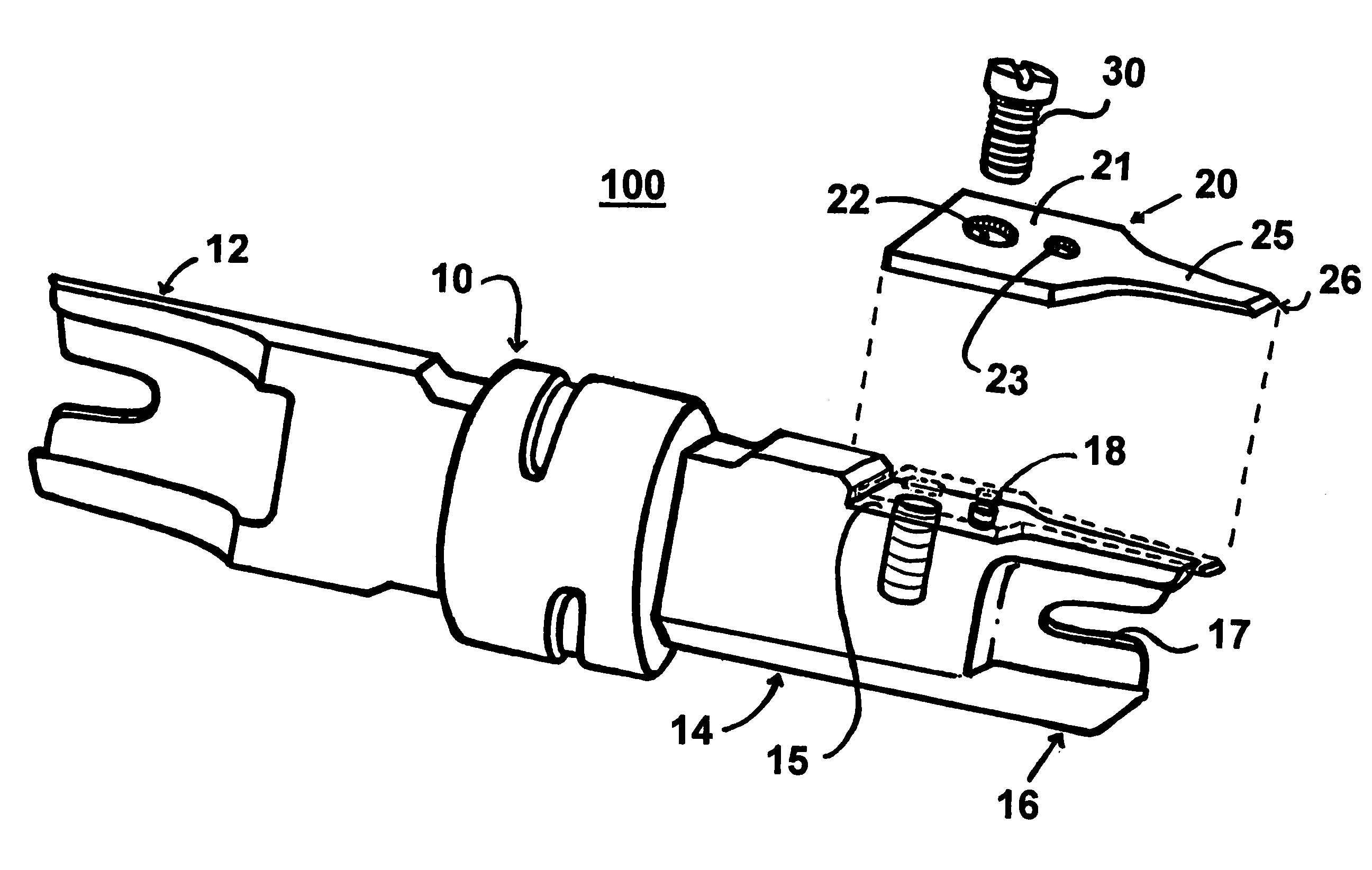
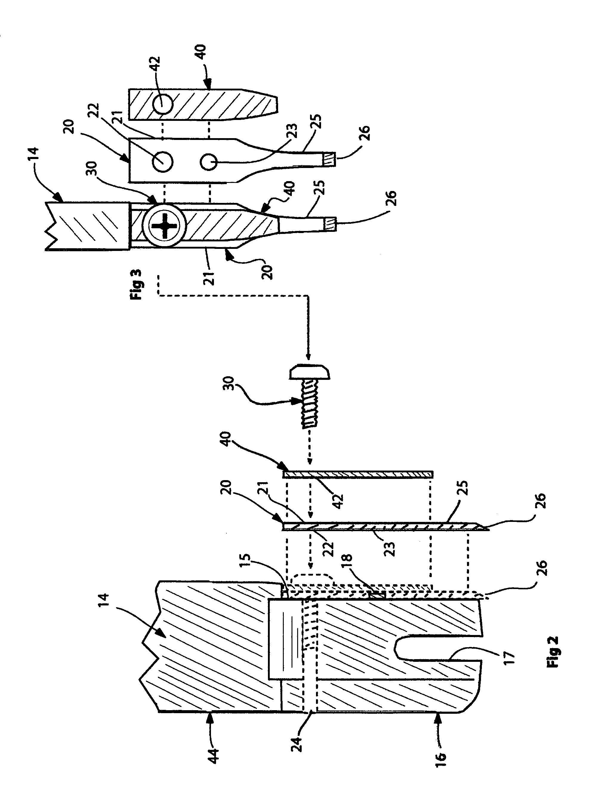
[0022]Referring now to FIG. 1 of the drawings, the presently preferred embodiment of my termination tool will now be described. The tool assembly 100 includes an elongated metal tool body 10 made of cast metal which is not heat treated. The tool body 10 has a positioning end 12, and a positioning and cutting end 14. The separate positioning end 12 is provided in accordance with the known prior art practices. The cutting end 14 has a side surface 15, and also has a forward end portion 16 with a U-shaped opening 17 that can partially encircle the end of a wire while forcing the wire to conductively engage an insulation displacing connector. Cutting end also has a hole 24 to receive a screw 30, as will be described. It also has a riser or locator pin 18 for securing the cutting blade in place, as will be described.

[0023]My replaceable blade member 20 is made of tool grade steel. It is of essentially flat configuration and has a wide rearward end portion 21 and a much narrower for...


PUM

PropertyMeasurementUnit
Rockwell hardnessaaaaaaaaaa
lengthaaaaaaaaaa
speedaaaaaaaaaa

Abstract

A tool assembly includes an elongated metal tool body for forcibly inserting the end of an insulated wire into a telephone connector of the insulation displacing type, and having a separate and replaceable cutting blade removably attached to the tool body for cutting off the then protruding end of the insulated wire after electrically conductive engagememnt of the wire with the blades of the connector has been achieved.

Description

PRIORITY CLAIM[0001]This application claims the priority of my U.S. Provisional Application Ser. No. 60 / 514,047 filed Oct. 24, 2003.FIELD OF THE INVENTION[0002]The field of this invention is tools for wiring telephone circuits or the like.BACKGROUND OF THE INVENTION[0003]In terminating telephone or high-speed data wires in a terminal block, an insulated end of each wire is forced into a insulation displacing type of connector that is mounted in and a part of a circuit board. A presently conventional tool system employs a hand piece to generate an impact force on a tool body, and the tool body in turn applies the same impact force to the end of the wire to force it into the connector. Forcing the wire into the connector also cuts the insulating cover of the wire, so that there is then an electrically conductive engagememnt of the wire with the connector blades. When the wire end is properly seated in the connector it is then also necessary to cut off a protruding end portion of the i...

Claims


Application Information

Patent Timeline
Patent Type & Authority Patents(United States)
IPC IPC(8): B23P23/00H01R43/00H01R43/01
CPCH01R43/01Y10T29/53222Y10T29/515Y10T29/5151
Inventor SULLIVAN, ROBERT W.
Owner SULLSTAR TECH
Why Eureka
Try Eureka