High thrust gas turbine engine with improved core system

a gas turbine engine and core system technology, applied in the direction of machines/engines, efficient propulsion technologies, light and heating equipment, etc., can solve the problem of increasing the difficulty of obtaining further improvements

Inactive Publication Date: 2006-08-29
GENERAL ELECTRIC CO
View PDF34 Cites 34 Cited by
  • Summary
  • Abstract
  • Description
  • Claims
  • Application Information

AI Technical Summary

Benefits of technology

[0010]In accordance with a third embodiment of the present invention, a gas turbine engine is disclosed as including: a compressor positioned at a forward end of the gas turbine engine having a plurality of stages, each stage including a stationary compressor blade row and a rotatable blade row connected to a first drive shaft and interdigitated with the first compressor blade row; a core system positioned downstream of the compressor, where the core system further includes an intermediate compressor positioned downstream of and in flow communication with the compressor connected to a second drive shaft and a combustion system for producing pulses of gas having increased pressure and temperature from a fluid supplied to an inlet thereof so as to produce a working fluid at an outlet; a low pressure turbine downstream of and in flow communication with the intermediate turbine for powering the first drive shaft; and, a load connected to the first drive shaft. An intermediate turbine may be positioned downstream of the combustion system in flow communication with the working fluid, where the intermediate turbine is utilized to power the second drive shaft. A first source of compressed air having a predetermined pressure is provided to the combustion system and a second source of compressed air having a pressure greater than compressed air from the first source is provided to cool the combustion system.

Problems solved by technology

While engines based on the Brayton Cycle have reached a high level of thermodynamic efficiency by steady improvements in component efficiencies and increases in pressure ratio and peak temperature, further improvements are becoming increasingly more difficult to obtain.

Method used


Image

  • High thrust gas turbine engine with improved core system
  • High thrust gas turbine engine with improved core system
  • High thrust gas turbine engine with improved core system

Examples


Embodiment Construction

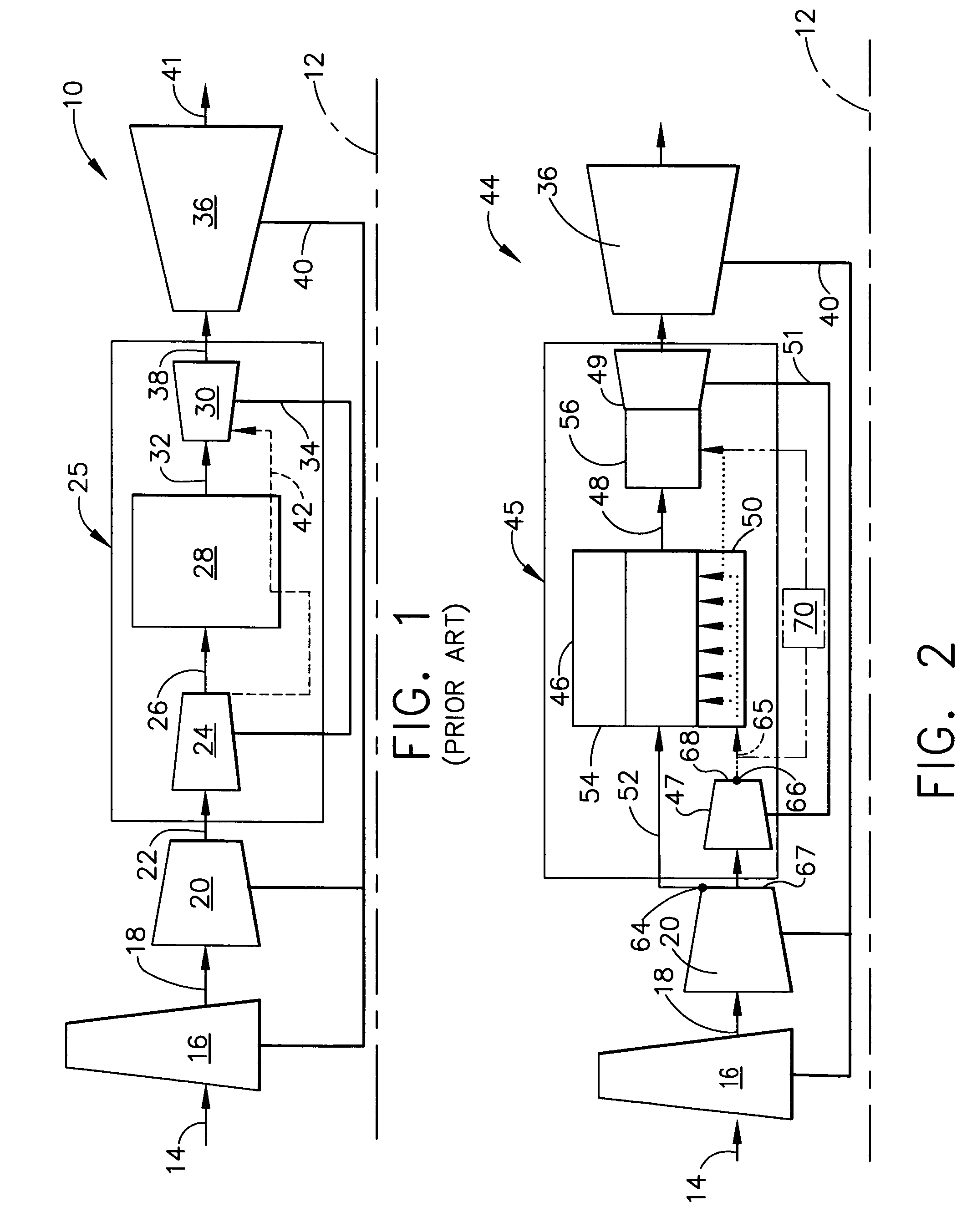
[0017]Referring now to the drawings in detail, wherein identical numerals indicate the same elements throughout the figures, FIG. 1 diagrammatically depicts a conventional gas turbine engine 10 (high bypass type) utilized with aircraft having a longitudinal or axial centerline axis 12 therethrough for reference purposes. A flow of air (represented by arrow 14) is directed through a fan section 16, with a portion thereof (represented by arrow 18) being provided to a booster compressor 20. Thereafter, a first compressed flow (represented by arrow 22) is provided to a core or high pressure system 25.

[0018]More specifically, core system 25 includes a high pressure compressor 24 which supplies a second compressed flow 26 to a combustor 28. It will be understood that combustor 28 is of the constant pressure type which is well known in the art. A high pressure turbine 30 is positioned downstream of combustor 28 and receives gas products (represented by arrow 32) produced by combustor 28 an...


PUM


Abstract

A gas turbine engine having a longitudinal centerline axis therethrough, including: a fan section at a forward end of the gas turbine engine including at least a first fan blade row connected to a first drive shaft; a booster compressor positioned downstream of and in at least partial flow communication with the fan section including a plurality of stages, each stage including a stationary compressor blade row and a rotating compressor blade row connected to a drive shaft and interdigitated with the stationary compressor blade row; a core system positioned downstream of the compressor, where the core system further includes an intermediate compressor positioned downstream of and in flow communication with the booster compressor, the intermediate compressor being connected to a second drive shaft, and a combustion system for producing pulses of gas having increased pressure and temperature from a fluid flow provided to an inlet thereof so as to produce a working fluid at an outlet; and, a low pressure turbine positioned downstream of and in flow communication with the core system, the low pressure turbine being utilized to power the first drive shaft. The core system may also include an intermediate turbine positioned downstream of the combustion system in flow communication with the working fluid, where the intermediate turbine is utilized to power the second drive shaft. A first source of compressed air having a predetermined pressure is provided to the combustion system inlet and a second source of compressed air having a pressure greater than the first source of compressed air is provided to cool the combustion system.

Description

BACKGROUND OF THE INVENTION[0001]The present invention relates generally to a high thrust gas turbine engine design and, in particular, to an improved core system which replaces the high pressure system of conventional gas turbine engines. An intermediate compressor of the gas turbine engine is associated with the core system to provide additional thrust while mitigating various effects from the combustion system so as to retain a low pressure turbine having a conventional design.[0002]It is well known that typical gas turbine engines are based on the ideal Brayton Cycle, where air is compressed adiabatically, heat is added at constant pressure, the resulting hot gas is expanded in a turbine, and heat is rejected at constant pressure. The energy above that required to drive the compression system is then available for propulsion or other work. Such gas turbine engines generally rely upon deflagrative combustion to burn a fuel / air mixture and produce combustion gas products which tra...

Claims


Application Information

Patent Timeline
Patent Type & Authority Patents(United States)
IPC IPC(8): F02C6/08
CPCF02C5/00F02C7/18F23R3/005F23R3/04F23R7/00F05D2260/20F23R2900/03044F23R2900/03281Y02T50/676F05D2260/96Y02T50/60
Inventor ORLANDO, ROBERT JOSEPHVENKATARAMANI, KATTALAICHERI SRINIVASANLEE, CHING-PANGMONIZ, THOMAS ORYMURROW, KURT DAVID
Owner GENERAL ELECTRIC CO
Why Eureka
Try Eureka