Seat-load measuring apparatus

a measuring apparatus and seat-load technology, applied in the direction of instruments, pedestrian/occupant safety arrangements, apparatus for force/torque/work measurement, etc., can solve the problems of reducing the strength of the base member, the limitation of the strength of the pin bracket 108, etc., to achieve sufficient measuring accuracy, prevent assembly stress, and increase mounting flexibility

Active Publication Date: 2006-08-29
JOYSON SAFETY SYST JAPAN GK
View PDF9 Cites 9 Cited by
  • Summary
  • Abstract
  • Description
  • Claims
  • Application Information

AI Technical Summary

Benefits of technology

[0013]Several exemplary objects of the present invention are to provide a seat-load measuring apparatus that can prevent assembly stress due to the influence of a vehicle body to ensure a sufficient measuring accuracy, that can increase mounting flexibility without increasing layout restrictions, and that can more reliably support a heavy load, for example, in a vehicle collision.

Problems solved by technology

Therefore, the pin bracket 108 has a limitation of having a sufficient strength.
In the seat-load measuring apparatus disclosed in Patent Document 2, however, an operation hole or the like must be formed in the base member, in a manner similar to that in Patent Document 1 described above, and this decreases the strength of the base member.

Method used


Image

  • Seat-load measuring apparatus
  • Seat-load measuring apparatus
  • Seat-load measuring apparatus

Examples


Embodiment Construction

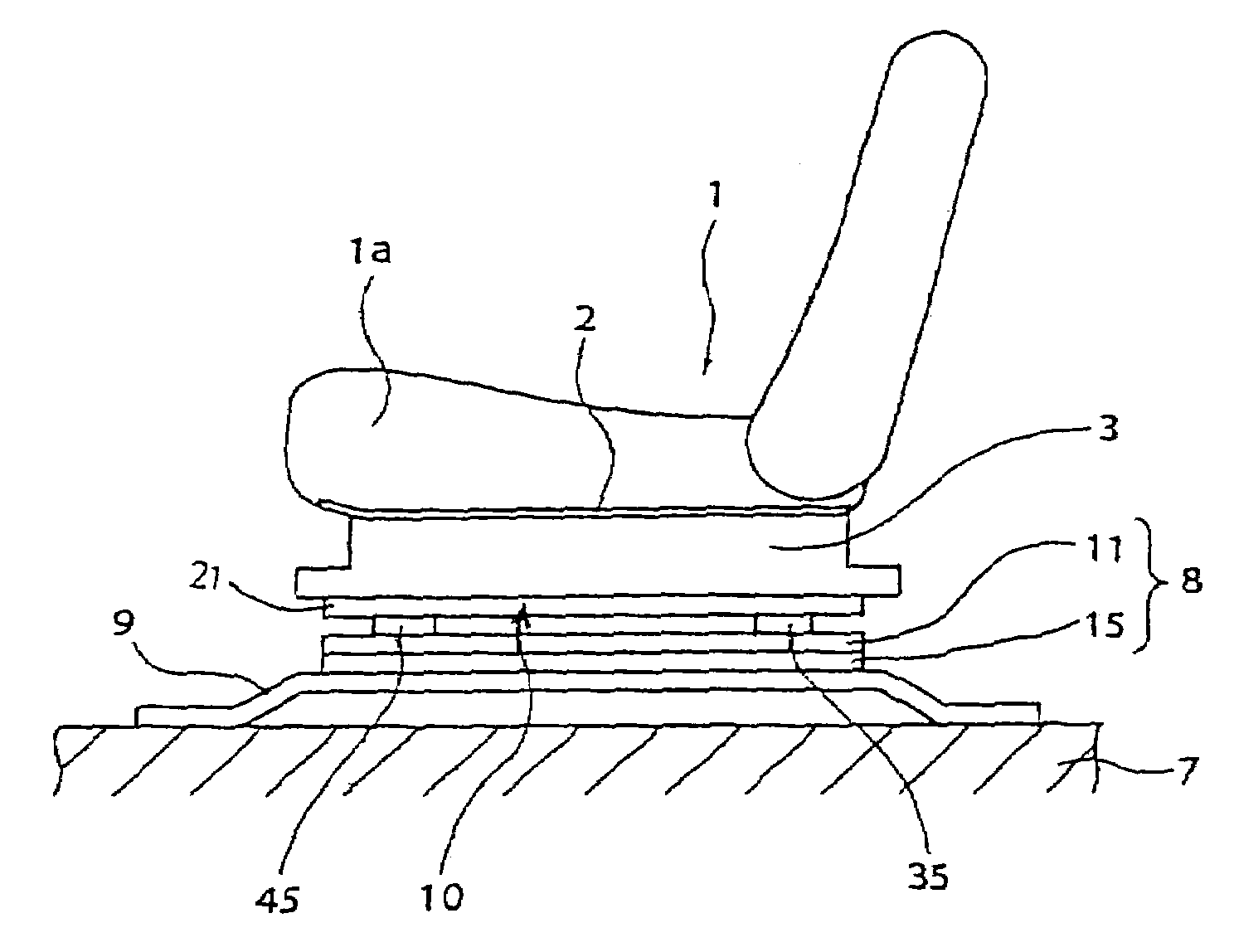
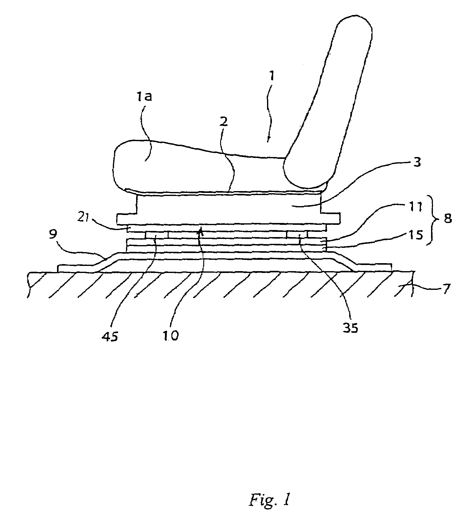
[0034]An embodiment of the present invention will be described below with reference to the drawings. Throughout the description, “front, rear, left, right, upper, and lower” sides refer to “front, rear, left, right, upper, and lower” sides of a vehicle.

[0035]As shown in FIG. 1, a seat pan 2 made of a steel plate is provided under a seat cushion 1a of a vehicle seat 1 on which a passenger sits so as to cover the entire lower surface of the seat cushion 1a. A pair of side frames 3 (only the left side frames is shown in FIG. 1) hang under the seat pan 2 with a predetermined space therebetween in the vehicle right-left direction. These side frames 3 extend in the front-rear direction of the vehicle.

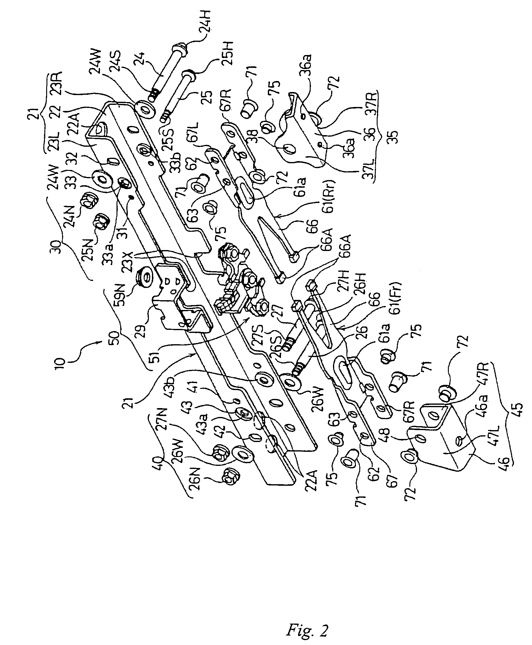
[0036]Seat-load measuring apparatuses 10 (only the left seat-load measuring apparatuses is shown in FIG. 1) are provided at the lower ends of the side frames 3 with a pair of front and rear mounting brackets 45 and 35 extending in the vehicle right-left direction therebetween. Base frames or ...


PUM


Abstract

A seat load measuring apparatus that includes a seat rail between a seat-load measuring apparatus and a vehicle floor. The apparatus includes a base frame and a base bracket that provide a load support mechanism to support a load heavier than a predetermined load imposed on the vehicle seat.

Description

BACKGROUND[0001]The present invention relates to a seat-load measuring apparatus mounted under a seat rail for guiding a seat of a vehicle, such as a car, so as to measure the load imposed on the vehicle seat.[0002]As this type of seat-load measuring apparatus, seat-load measuring apparatuses 104 have been proposed which are mounted under seat rails 103 for guiding a vehicle seat 102, on which a person 101 sits, in order to measure the load imposed on the vehicle seat 102, as shown in FIGS. 10(A) to 10(C) (for example, see Japanese Unexamined Patent Application Publication No. 2000-258234, hereinafter “Patent Document 1”).[0003]In each seat-load measuring apparatus 104, a lower surface of a base 105 that has an upward-pointing angular-U shape in cross section is fixed to a seat mounting section 107 of a vehicle body with seat brackets 106 at the front and rear ends therebetween, and the seat rail 103 and the base 105 are connected by a pin bracket (hereinafter, also referred to as a...

Claims


Application Information

Patent Timeline
Patent Type & Authority Patents(United States)
IPC IPC(8): G01D7/00B60N2/90B60R21/16G01G23/02G01G19/12G01G19/414G01G19/52
CPCG01G19/4142
Inventor KOBATA, TOSHIHIKO
Owner JOYSON SAFETY SYST JAPAN GK
Why Eureka
Try Eureka