
Automatic top slice removal device

a top slice and automatic technology, applied in the field of meat product cutting devices, to achieve the effect of reducing waste and inefficiency, simple design, and long usable li

Active Publication Date: 2006-08-29
JOHN BEAN TECH CORP
View PDF4 Cites 9 Cited by
  • Summary
  • Abstract
  • Description
  • Claims
  • Application Information

AI Technical Summary

Benefits of technology

The present invention is an automatic top slice removal device that reduces waste and inefficiency in the production of meat products. It includes a frame, lower conveyor belt, upper conveyor belt, and a top slice separator plate. The device also has a top slice removal conveyor belt that removes the top slice from the remainder of the meat product. The invention simplifies the process of removing the top slice and can be used with different types of meat products. It also improves processing efficiency and does not impede the processing line.

Problems solved by technology

Despite the fact that this type of labor is generally unskilled, it still must be performed to ensure proper functioning of the packing plant and thus the meat packing plant must provide a worker to perform this waste material removal process.
When one adds up the total number of workers needed to remove waste meat products from these slicing and cutting devices, it is seen that a large percentage of the workers on the cutting room floor are involved in dealing with waste products which do not produce any substantial income for the meat packing plant.
These devices are not designed to remove the waste products from the cutting process and transfer them to a separate processing location and even those devices in the prior art specifically designed for removal of specific waste product pieces are generally not designed for removal of the waste product piece to a different processing location.
The dangers inherent in this procedure are readily apparent and include the machine operator possibly cutting him or herself on the bandsaw, the operator being caught up in the conveyor belt system trying to remove the top slice from the butt section or many other possible dangers encountered when the extremities of the operator must be inserted into the slicing and transporting machinery.

Method used


Image

  • Automatic top slice removal device
  • Automatic top slice removal device
  • Automatic top slice removal device

Examples


Embodiment Construction

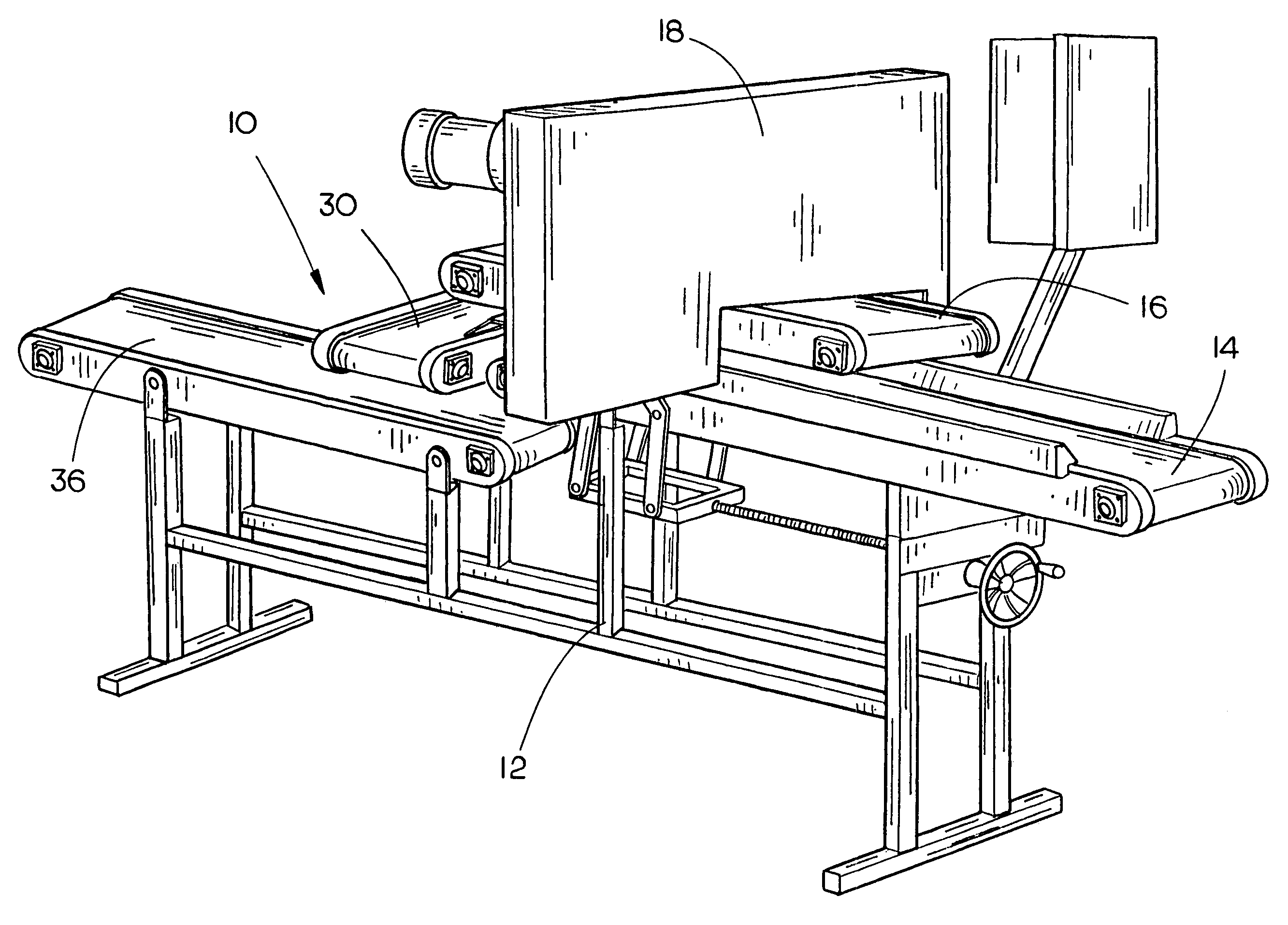
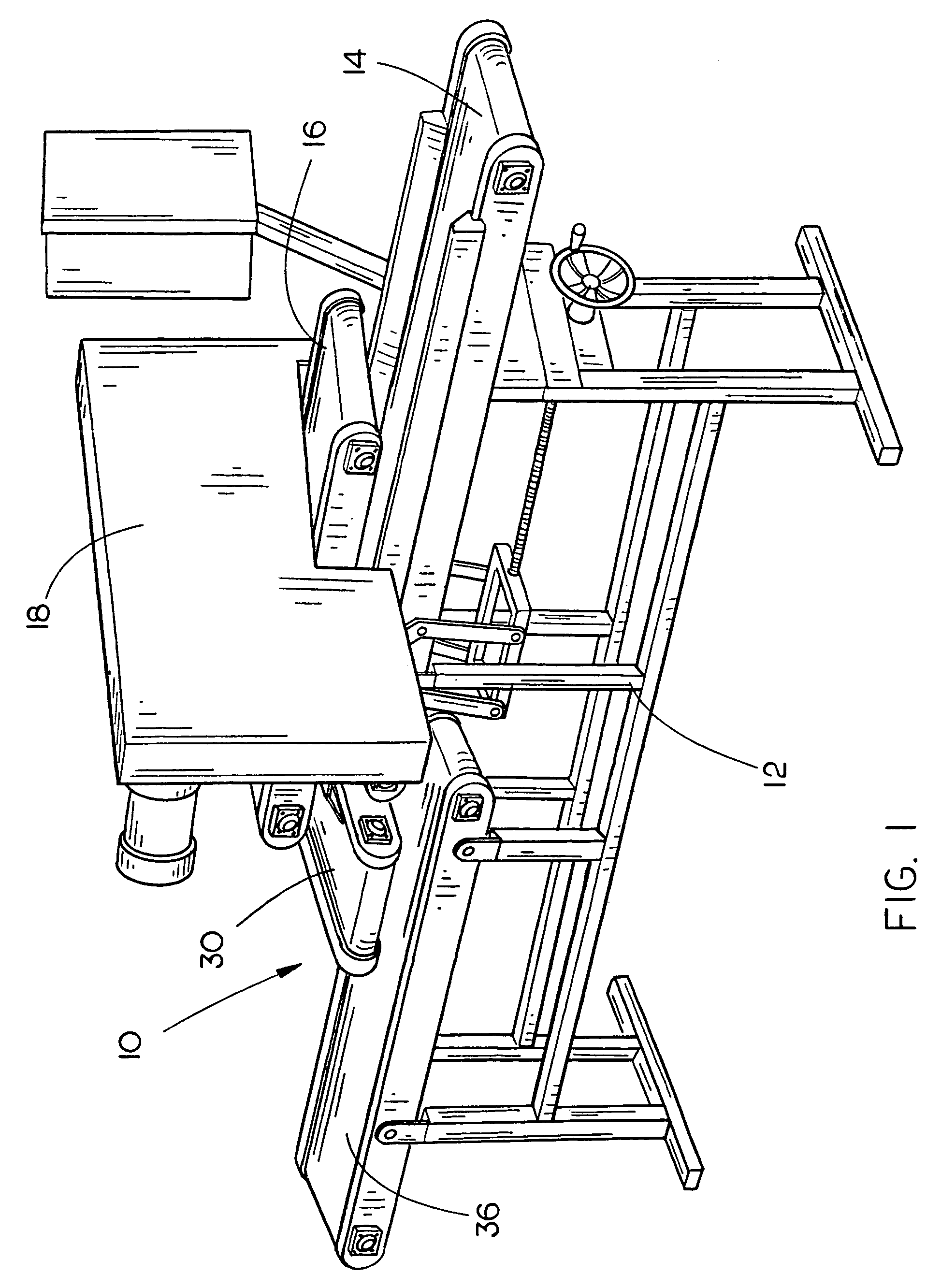
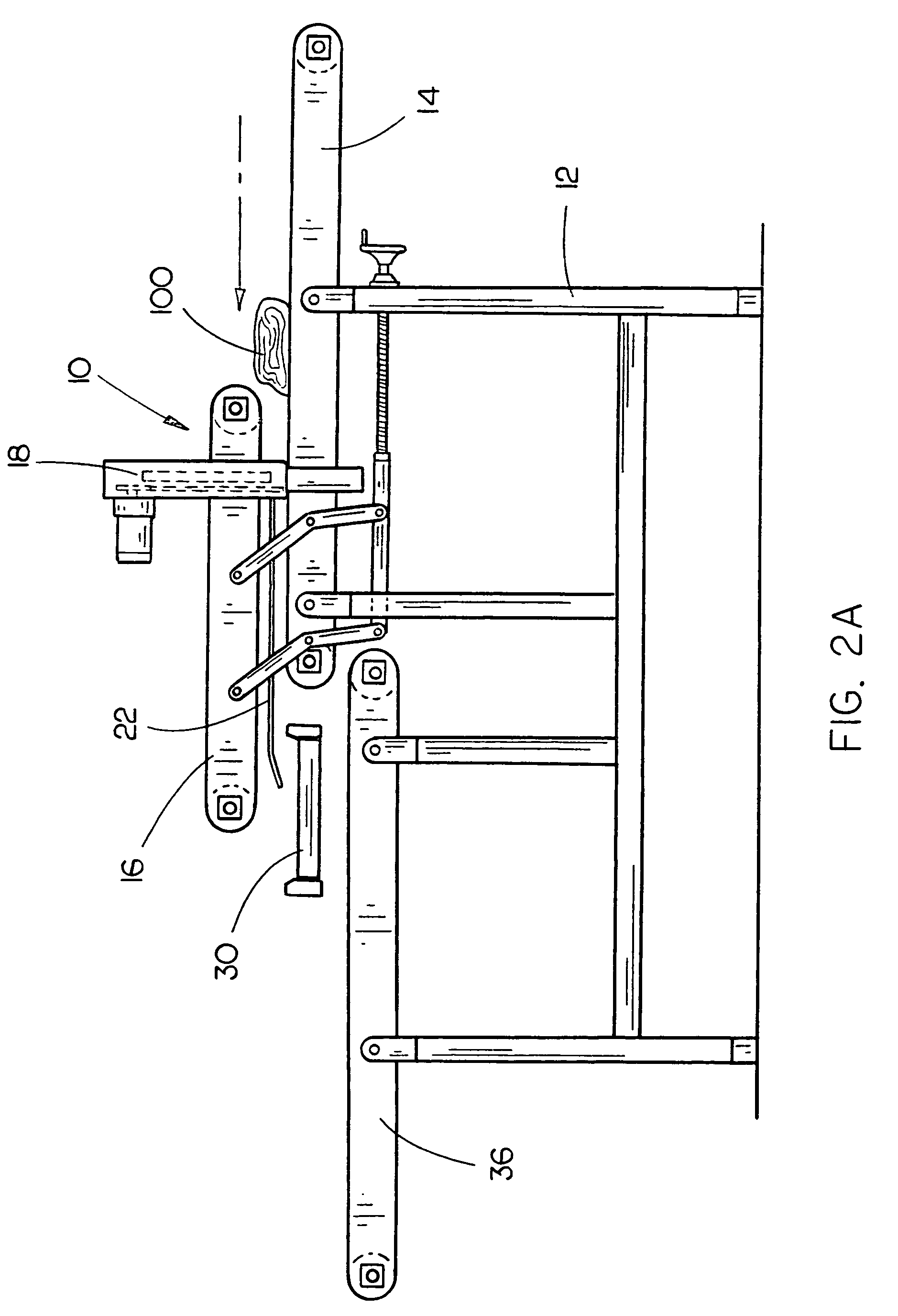
[0016]The top slice removal device 10 of the present invention is shown best in FIGS. 1–3 as including a frame 12 on which the device 10 rests and two conveyor belts, a lower conveyor belt 14 extending generally horizontally and an upper conveyor belt 16 adjustably mounted above and extending generally parallel with the lower conveyor belt 14. In the preferred embodiment, the lower and upper conveyor belts 14 and 16 would have lengths of approximately two feet to five feet, with the lower conveyor belt 14 extending forwards of the upper conveyor belt 16 to facilitate the placement of meat product thereon, and widths of approximately fifteen inches to thirty inches, depending on the meat product to be processed and the space available on the cutting floor for the top slice removal device 10. Furthermore, it should be noted that the use of lower and upper conveyor belts 14 and 16 to securely transport meat product therebetween is well known in the prior art and therefore the specific ...


PUM

PropertyMeasurementUnit
widthsaaaaaaaaaa
widthsaaaaaaaaaa
lengthsaaaaaaaaaa

Abstract

An automatic top slice removal device includes a frame, a lower conveyor belt and an adjustably mounted upper conveyor belt extending generally parallel with and spaced from the lower conveyor belt. A meat product slicing device includes a blade interposed between the upper conveyor belt and the lower conveyor belt to separate a top slice from the remainder of the meat product. A top slice separator plate is adjustably mounted between the upper conveyor belt and the lower conveyor belt and positioned rearwardly adjacent and vertically aligned with the blade and extends rearwards therefrom to maintain separation of the top slice and the remainder of the meat product between the belts. Finally, a top slice removal conveyor belt is positioned rearwards of the top slice separator plate and below the upper conveyor belt to remove the top slice from the remainder of the meat product.

Description

BACKGROUND OF THE INVENTION[0001]1. Technical Field[0002]The present invention is related to meat product cutting devices and, more particularly, to a top slice removal device which includes a frame, a lower conveyor belt mounted on the frame, an upper conveyor belt extending generally parallel with and spaced from the lower conveyor belt, a slicing device such as a bandsaw interposed between the upper and lower conveyor belts, a top slice separator plate adjustably mounted between the upper and lower conveyor belts, a top slice removal conveyor belt positioned rearwards of the separator plate for transporting the top slice for further processing and a rear conveyor belt for transferring the remainder of the meat product for further processing.[0003]2. Description of the Prior Art[0004]The meat packing industry has numerous types of slicing and cutting devices each designed to perform a specific function such as cutting a particular type of meat product or removing and separating on...

Claims


Application Information

Patent Timeline
Patent Type & Authority Patents(United States)
IPC IPC(8): A22C17/00B26D3/28B26D7/06B26D7/32
CPCB26D3/28Y10S83/932B26D7/32Y10T83/2074Y10T83/2087Y10T83/2187Y10T83/6633Y10T83/722
Inventor BIGGS, HENRYKORTELEY, STEVE
Owner JOHN BEAN TECH CORP
Learn More