Car air conditioner

Inactive Publication Date: 2006-08-29
ZEXEL VALEO CLIMATE CONTROL CORP SAITAMA
View PDF10 Cites 11 Cited by
  • Summary
  • Abstract
  • Description
  • Claims
  • Application Information

AI Technical Summary

Benefits of technology

[0137]According to the sixth embodiment, the same advantageous effects as provided by the fifth embodiment can be obtained.
[0138]FIG. 10 is a longitudinal cross-sectional view of an automotive air conditioner according to a seventh embodiment of the invention. In FIG. 10, illustration of the instrument panel IP, the cowl Ca, the fire panel Fi, and the floor panel Fl is omitted. The component parts common to those in the first embodiment are designated by identical reference numerals and description thereof is omitted.
[0139]In the seventh embodiment, a hole TH formed by a hollow cylindrical portion 52 as the steering member-accommodating portion, the steering member interference-avoiding portion, or the steering member-arranging space portion is located above the heater core 7 or within the air-mixing space. A casing 61 is configured such that it can be divided in the front-rear direction BB of the vehicle into a fire panel-side part Fp and an instrument panel-side part Rp with the hole TH accommodating the steering member S as a boundary.
[0140]This seventh embodiment is the same as the sixth embodiment except for the manner of division.
[0141]According to the seventh embodiment, the same advantageous effects as provided by the third embodiment can be obtained.
[0142]FIG. 11 is a longitudinal cross-sectional view of an automotive air conditioner according to an eighth embodiment of the invention. In FIG. 11, illustration of the instrument panel IP, the cowl Ca, the fire panel Fi, and the floor panel Fl is omitted. The component parts common to those in the first embodiment are designated by identical reference numerals and description thereof is omitted.

Problems solved by technology

As a result, when an attempt is made to first mount the automotive air conditioner on the vehicle, and then mount the steering member S, the steering member S is interfered with the automotive air conditioner, and hence cannot be mounted.
Inversely, when an attempt is made to first mount the steering member S on the vehicle, and then mount the automotive air conditioner, the automotive air conditioner is interfered with the steering S and hence cannot be mounted.
As described above, a change in the mounting location of the steering member S has brought about a problem that both the air conditioner and the steering member S cannot be installed on the vehicle.

Method used


Image

  • Car air conditioner
  • Car air conditioner
  • Car air conditioner

Examples


first embodiment

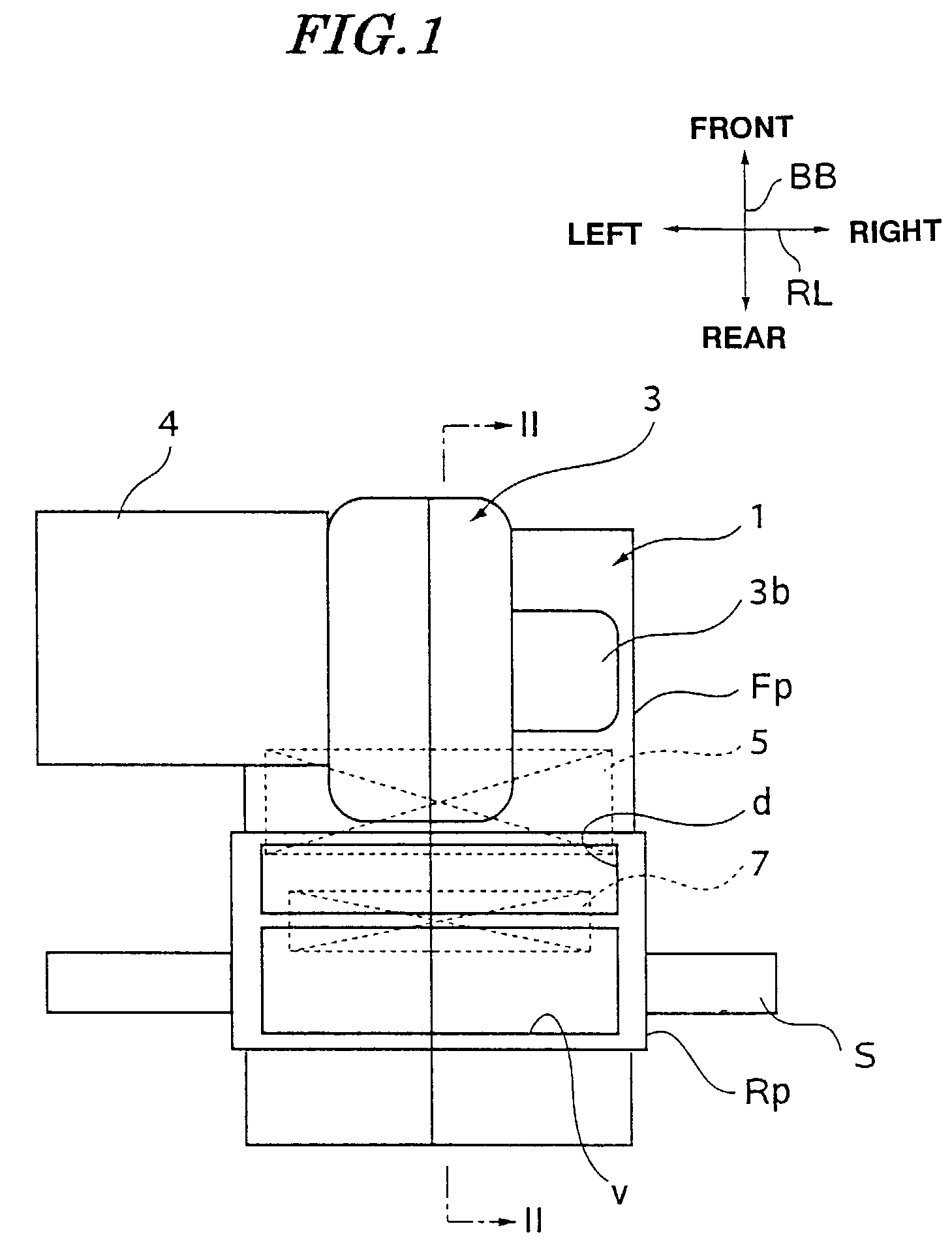
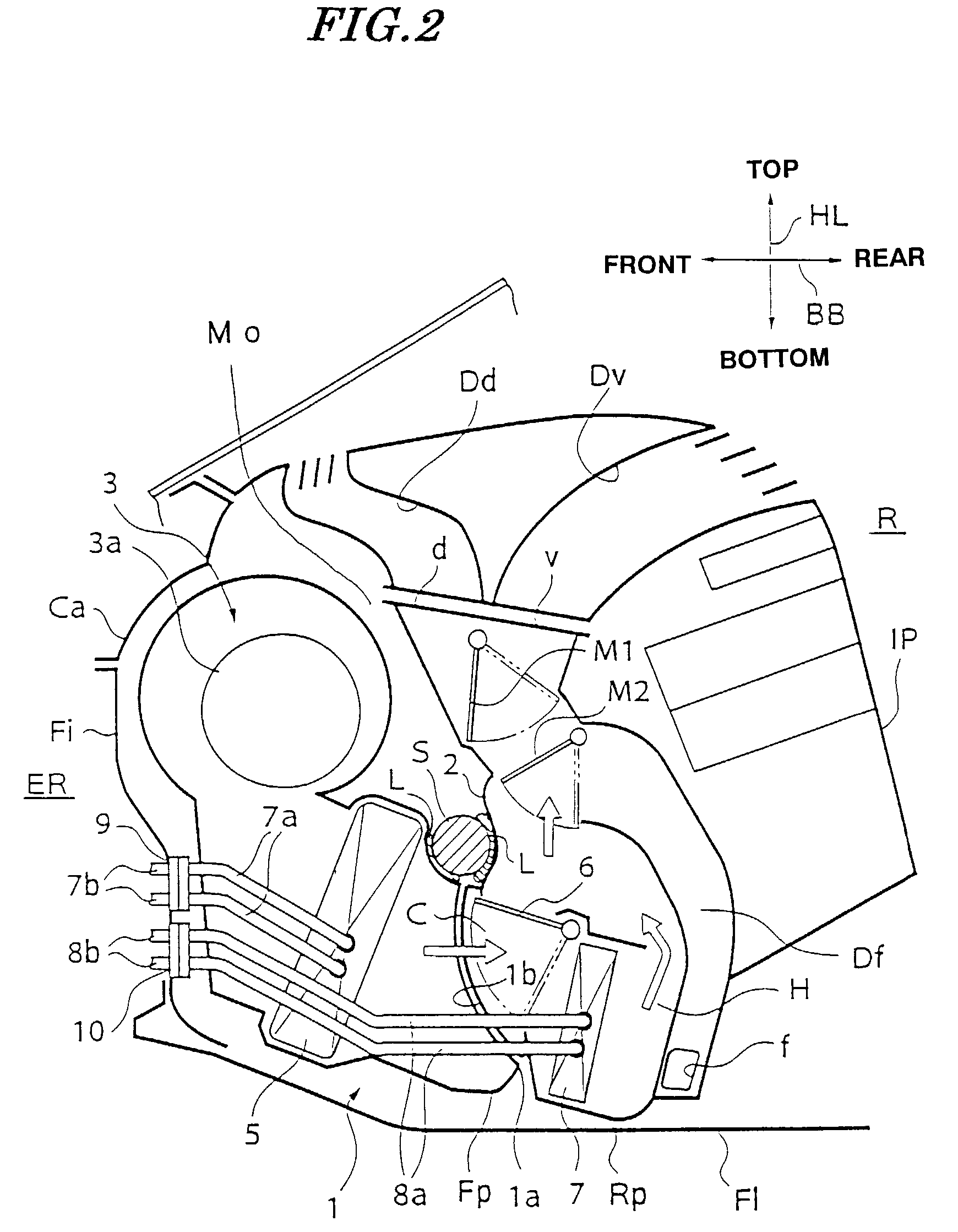
[0067]FIG. 1 is a plan view of an automotive air conditioner according the invention, and FIG. 2 is a cross-sectional view taken on line II—II in FIG. 1.

[0068]This automotive air conditioner is received in a space defined by an instrument panel IP, a cowl Ca, a fire panel Fi, and a floor panel Fl.

[0069]The fire panel Fi divides between an engine room ER and a compartment R, while the floor panel Fl forms the floor of the compartment R. This automotive air conditioner and the instrument panel IP are located within the compartment R.

[0070]A steering member S is arranged at a location lower than and ahead of that of the conventional steering member S (see FIG. 29).

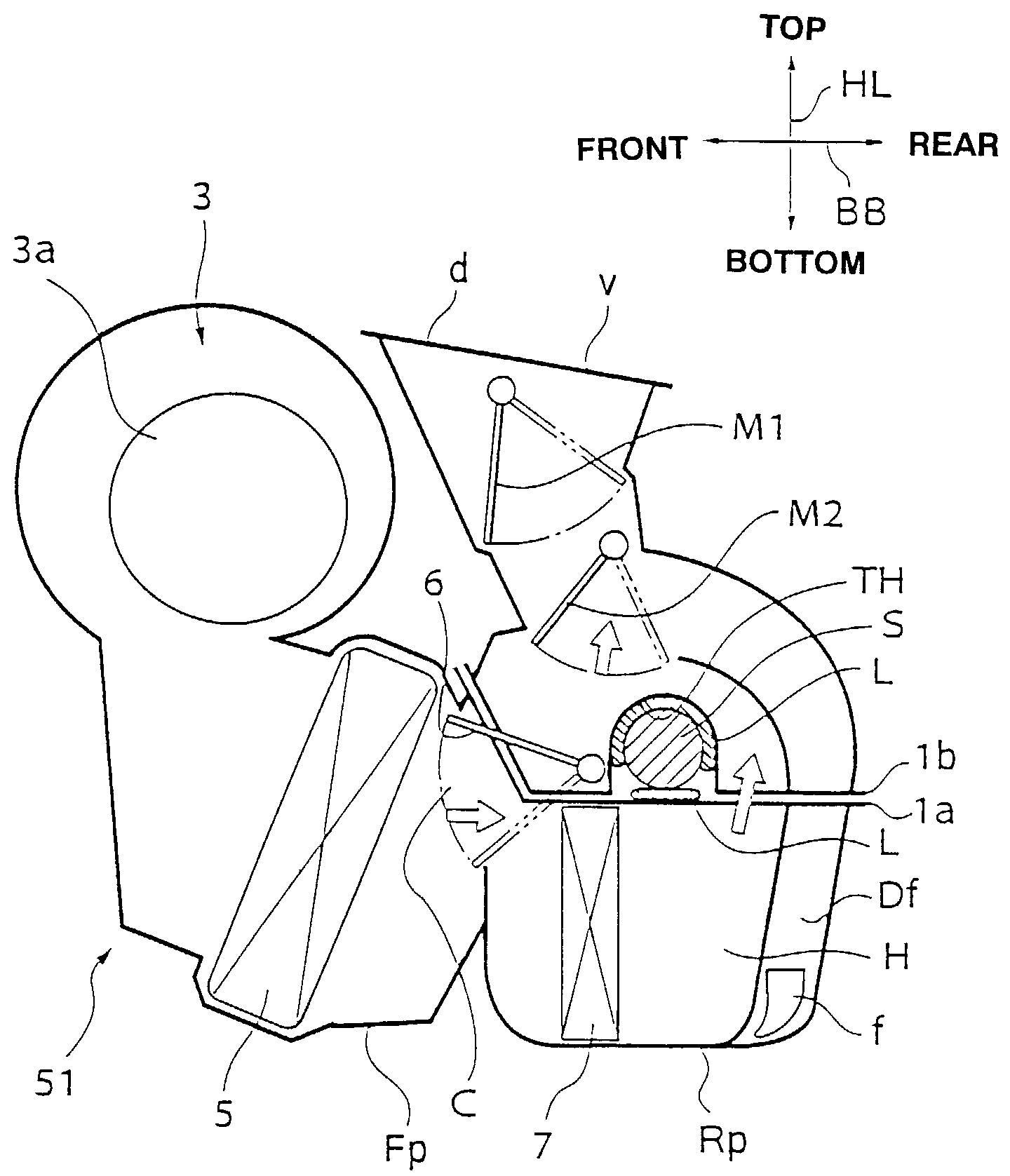
[0071]This automotive air conditioner has a casing 1 formed with a recess (steering member-accommodating portion) 2 for receiving the steering member S extending in a right-left direction RL of the vehicle. The steering member-accommodating portion may be formed by a hole TH as shown in FIG. 4 etc., instead of the recess 2. T...

second embodiment

[0083]It should be noted that the fire panel-side part Fp and the instrument panel-side part Rp can be each divided in the right-left direction RL of the vehicle, and the left and right casing component parts constituting the fire panel-side part Fp and the instrument panel-side part Rp are fixed in the right-left direction by fixing means (not shown), such as tapping screws. This feature of the construction commonly applies to the other embodiments of the invention including the

[0084]Next, a procedure of assembling the automotive air conditioner, the steering member S and so forth with a vehicle on a vehicle assembly line will be described.

[0085]First, the fire panel-side part Fp and the instrument panel-side part Rp of the automotive air conditioner are mounted on the vehicle. At this time, the fire panel-side part Fp is fixed to the fire panel Fi by bolts, and a connector 9 of a refrigerant pipe 7a of the evaporator 5 is fixed to the fire panel Fi. The refrigerant pipe 7a is conn...

third embodiment

[0115] the same effects as the effects (1) to (6) described above can be obtained.

[0116]The hole TH extending through the casing 21 in the right-left direction of the vehicle is employed as the steering member-accommodating portion, the steering member interference-avoiding portion, or the steering member-arranging space portion. Therefore, compared with the case in which the simple recess 12 as shown in FIG. 3 is employed, areas around the steering member S or a circular area surrounding the circumference of the steering member S can be utilized as the air passage. In this embodiment, the air passes above and below the steering member S. Therefore, it is possible to prevent an increase in the resistance to the flow of air through the air passage without increasing the size of the casing, and secure the performance of the air conditioner.

[0117]The air cooled by the evaporator 5 is divided by the hollow cylindrical portion 22 into upper and lower streams, and the cold air bypass pass...


PUM


Abstract

A casing 21 of an automotive air conditioner is formed with a hole TH for accommodating a steering member S extending in a right-left direction of a vehicle. The hole TH extends through the casing 1 in the right-left direction of the vehicle.

Description

[0001]This application is a U.S. National Phase Application under 35 USC 371 of International Application PCT / JP01 / 01949 filed Mar. 13, 2001.TECHNICAL FIELD[0002]This invention relates to an automotive air conditioner, and more particularly to an automotive air conditioner which cope with a change in the location of a steering member.BACKGROUND ART[0003]FIG. 29 is a longitudinal cross-sectional view of a conventional automotive air conditioner.[0004]This automotive air conditioner is arranged in a space defined by an instrument panel (not shown), a floor panel Fl, and a fire panel Fi.[0005]The fire panel Fi divides between an engine room ER and a compartment R, while the floor panel forms the floor of the compartment R. The automotive air conditioner and the instrument panel are located within the compartment R.[0006]A steering member S is located between the instrument panel and the automotive air conditioner.[0007]This automotive air conditioner has a casing 501 in which there are...

Claims


Application Information

Patent Timeline
IPC IPC(8): B60H1/00B62D25/14
CPCB62D25/14B60H1/00535
Inventor ARAKI, DAISUKENAGANO, HIDEKIYANAGIDA, EIJIKATCHI, KAZUHISANOGUCHI, AKITOSHINAKAMIGAWA, TSUTOMUYAMAMOTO, KATSUICHIMATSUMOTO, TAKEHIDE
Owner ZEXEL VALEO CLIMATE CONTROL CORP SAITAMA
Why Eureka
Try Eureka