Swing arm crane and method

a crane and swing arm technology, applied in the field of cranes and methods of using cranes, can solve the problems of bulky oil field equipment, inconvenient use of cranes and/or winches, and general ill suited and/or positioned air tuggers to lift this type of equipment, and achieve the effect of balanced mechanical design

Active Publication Date: 2006-08-29
DEVIN INT
View PDF6 Cites 24 Cited by
  • Summary
  • Abstract
  • Description
  • Claims
  • Application Information

AI Technical Summary

Benefits of technology

[0015]An advantage of the present invention is that an angle of rotation of 180 degrees is possible. Another advantage is that an operator may perform work within a work window and the swing arm crane can be pivoted outside the work window. Still yet another advantage is that the use of the device herein disclosed frees up other crane devices on a rig such as the air tuggers. Yet another advantage is that an operator may use power means that are already present on the rig, such as a hydraulic power source or a pneumatic power source.
[0016]A feature of the present invention includes use of a rotary actuator, such as a hydraulic motor, to pivot the arm. Another feature is that the arm freely rotates in an angle of rotation of at least 180 degrees. Still yet another feature is that the arm mounts to a support structure, such as a lift frame and the arm can rotate from an aft position to a fore position relative to the support structure. Yet another feature is that the winch, in one preferred embodiment, is attached to the bottom end of the arm, and the sheave is at the top end of the arm, thereby providing for a balanced mechanical design when lifting or lowering loads.

Problems solved by technology

However, oil field equipment is bulky.
Prior art cranes and / or winches needed to lift this equipment are inadequate.
However, air tuggers are generally ill suited and / or positioned for lifting this type of equipment.

Method used


Image

  • Swing arm crane and method
  • Swing arm crane and method
  • Swing arm crane and method

Examples


Embodiment Construction

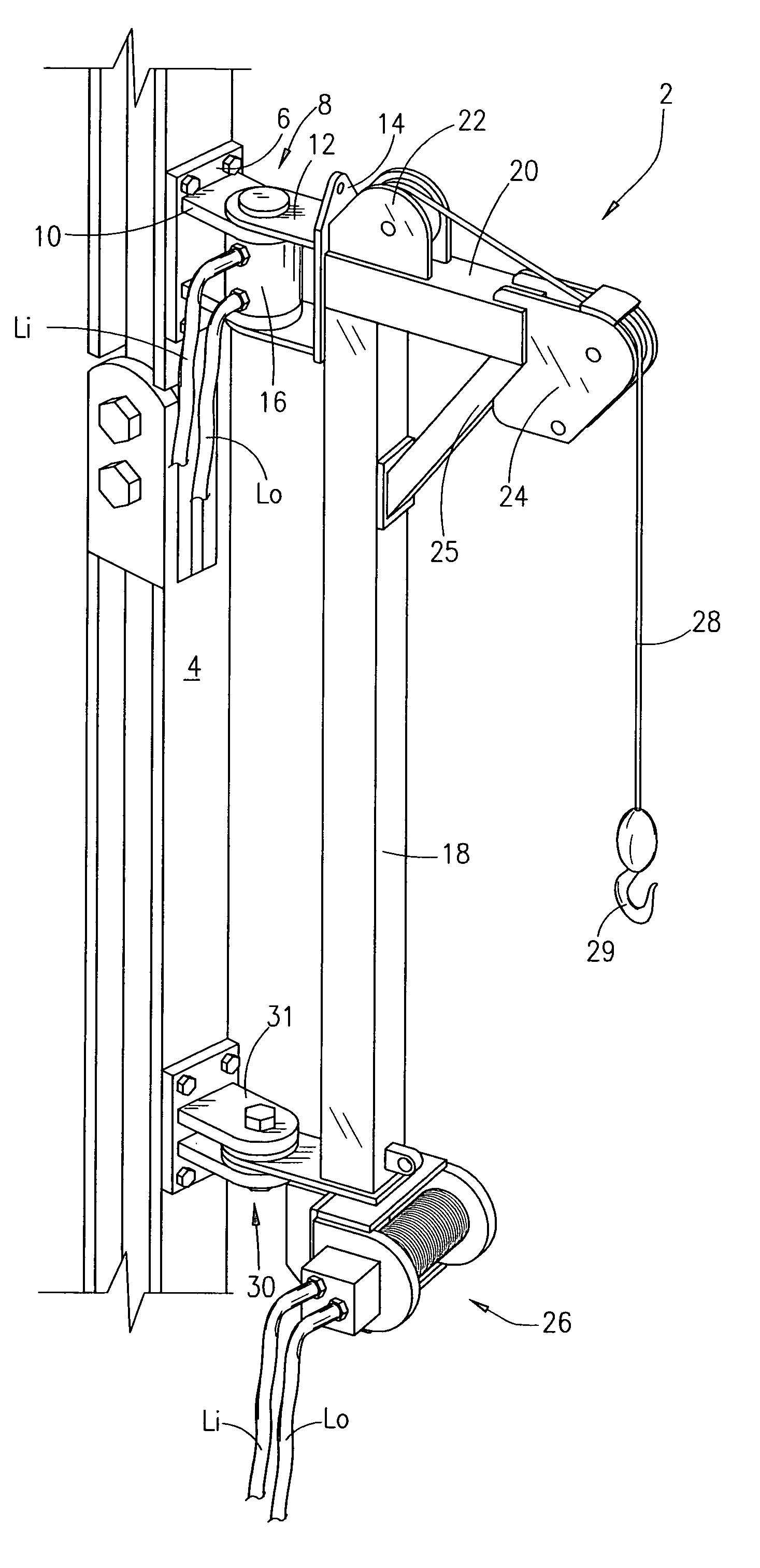
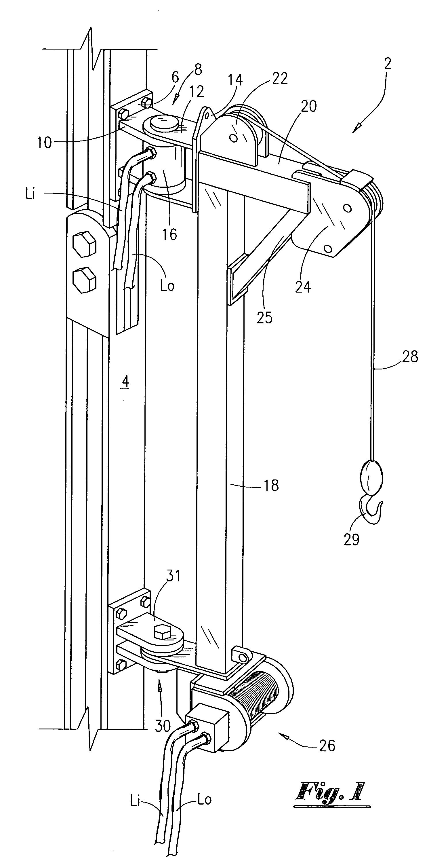
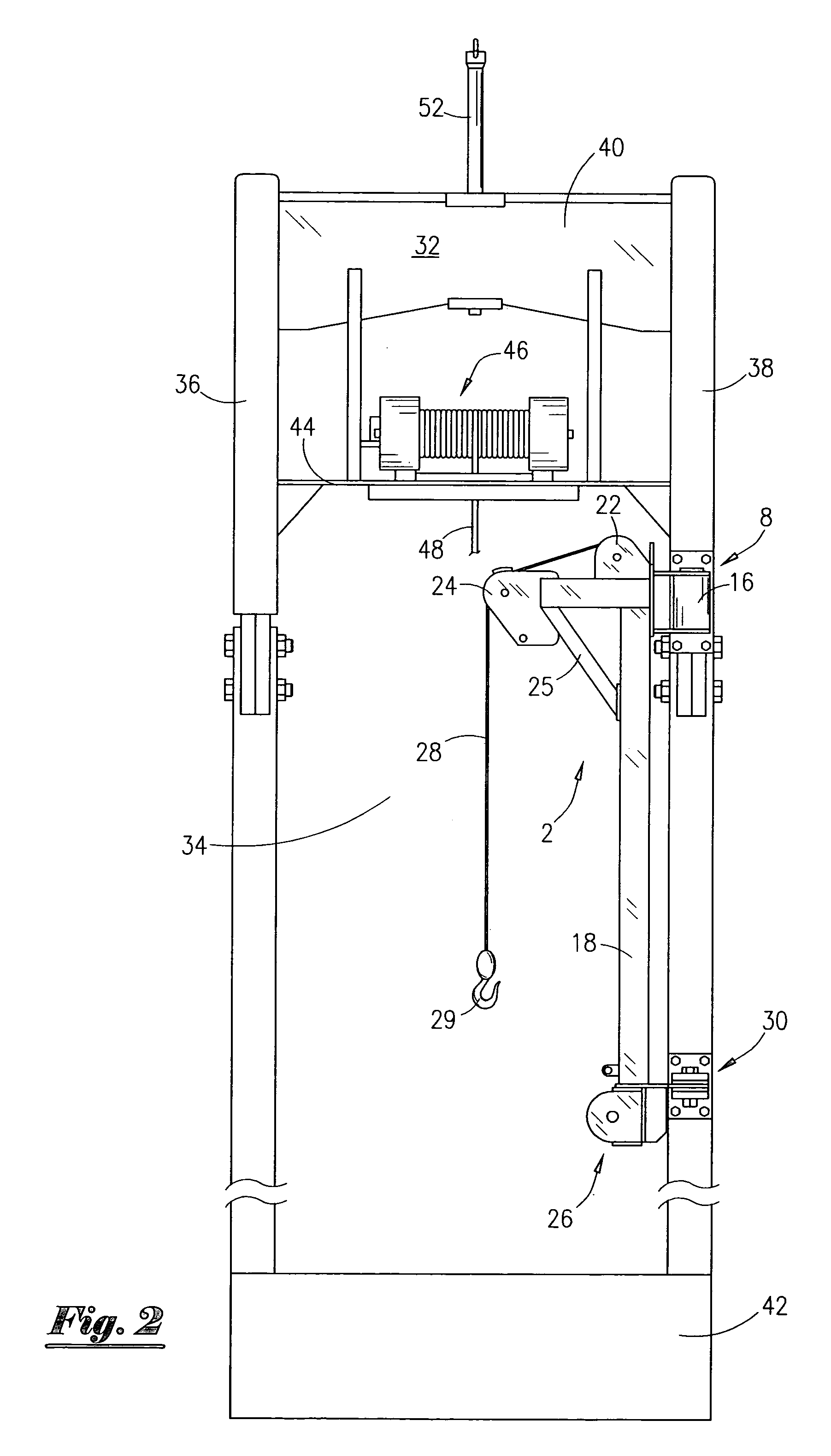
[0023]Referring now to FIG. 1, an isometric view of the swing arm crane 2 will now be described. The swing arm crane 2 is attached to a support structure 4. A base plate 6 is attached to the support structure 4 via nuts and bolts. Other attachment means are possible, such as attaching the base plate 6 via welding. The base plate 6 has a first hinge means 8 attached thereto, and wherein the first hinge means 8 has a first end 10 attached to the base plate 6 and a second end 12 connected to the attachment plate 14.

[0024]The first hinge means 8 will contain the rotary actuator means 16 for pivoting the swing arm 18, and wherein the arm 18 is pivotal from an area exterior of a working window area to an area within the working window area, as will be explained in greater detail later in the application. The rotary actuator means 16 is a hydraulic motor in one preferred embodiment, and wherein the motor is commercially available from Helac Corporation under the name Rotary Actuator (model...


PUM


Abstract

An apparatus for lifting and moving a load. The apparatus comprises a lift frame having a first and second vertical member that are connected so that a working window area is defined. The apparatus further comprises a rotary actuator mounted on the first vertical member, and an arm having a first end and a second end, and wherein the first end of the arm is pivotly connected to the rotary actuator. The arm is pivotal from an area exterior of the working window area to an area within the working window area. The apparatus may further comprise a winch, operatively attached to the arm, for lifting a load with the cable. A method of lifting a load is also disclosed.

Description

BACKGROUND OF THE INVENTION[0001]This invention relates to a crane and method of using a crane. More specifically, but not by way of limitation, this invention relates to a swing arm crane and a method of using the crane to lift loads on a rig.[0002]In the course of searching for oil and gas, operators drill in various regions of the globe, including the world's oceans. Many times, a floating type of drilling rig or floating production platform is utilized, as is well understood by those of ordinary skill in the art. During the course of drilling, completion, and / or production operations, operators may find it necessary to perform remedial well work.[0003]Remedial well work can be performed with a coiled tubing unit, a snubbing unit, workover rig, etc. In the use of a coiled tubing unit and / or snubbing unit, operators will rig up a lift frame within the derrick. The lift frame is used to support injector heads, lubricators, etc. during the rig up, operation and rig down phases of th...

Claims


Application Information

Patent Timeline
Patent Type & Authority Patents(United States)
IPC IPC(8): E21B23/00B66C23/20E21B19/00
CPCE21B19/00B66C23/208
Inventor MONCUS, JAMES DEVINMILLER, JR., JOSEPH HAYDEN
Owner DEVIN INT
Why Eureka
Try Eureka