Vented slot brake rotor

a brake rotor and venting technology, which is applied in the direction of brake elements, brake discs, brake types, etc., can solve the problems of reducing the heat dissipation surface area of the respective external braking surface, reducing the braking performance, and reducing the braking surface area, so as to increase the brake performance and the cooling efficiency of the brake rotor

Inactive Publication Date: 2006-08-29
LIN WARREN
View PDF16 Cites 39 Cited by
  • Summary
  • Abstract
  • Description
  • Claims
  • Application Information

AI Technical Summary

Benefits of technology

[0007]The present invention addresses the above problems of prior art brake rotors and presents novel rotors and methods for cooling, venting and / or cleaning of brake rotors. Specifically, embodiments of the present invention may not only increase brake performance and cooling efficiency of a brake rotor, but also may insure that slotted rotors remain free and clear of debris by causing the debris to be “suctioned” from the external braking surface of the rotor through an opening in the slot. Specifically, the opening may communicate with the vents of the rotor (in a vented rotor design), so that the airflow generated by the vents when the rotor is moving acts as a negative pressure force to draw material and gases from one or more slots.

Problems solved by technology

The use of slots and cross-drilled holes however, decreases the heat dissipation surface area of a respective external braking surface as well as decrease the braking surface area.
Either or both of these decreases in respective surface areas may result in a decrease in braking performance (e.g., increased braking distances).
Moreover, the more rotor material removed (by the creations of slots and / or the use cross-drilled holes), the more prone the rotor may be to premature failure due to thermal fatigue.
This may result in rotor warping.
Slotted rotors may also be prone to yet another problem.
Collected brake dust may ultimately clog one or more slots after time resulting in a decrease or cessation of the ability of the slot to perform this job.

Method used


Image

  • Vented slot brake rotor
  • Vented slot brake rotor
  • Vented slot brake rotor

Examples


Embodiment Construction

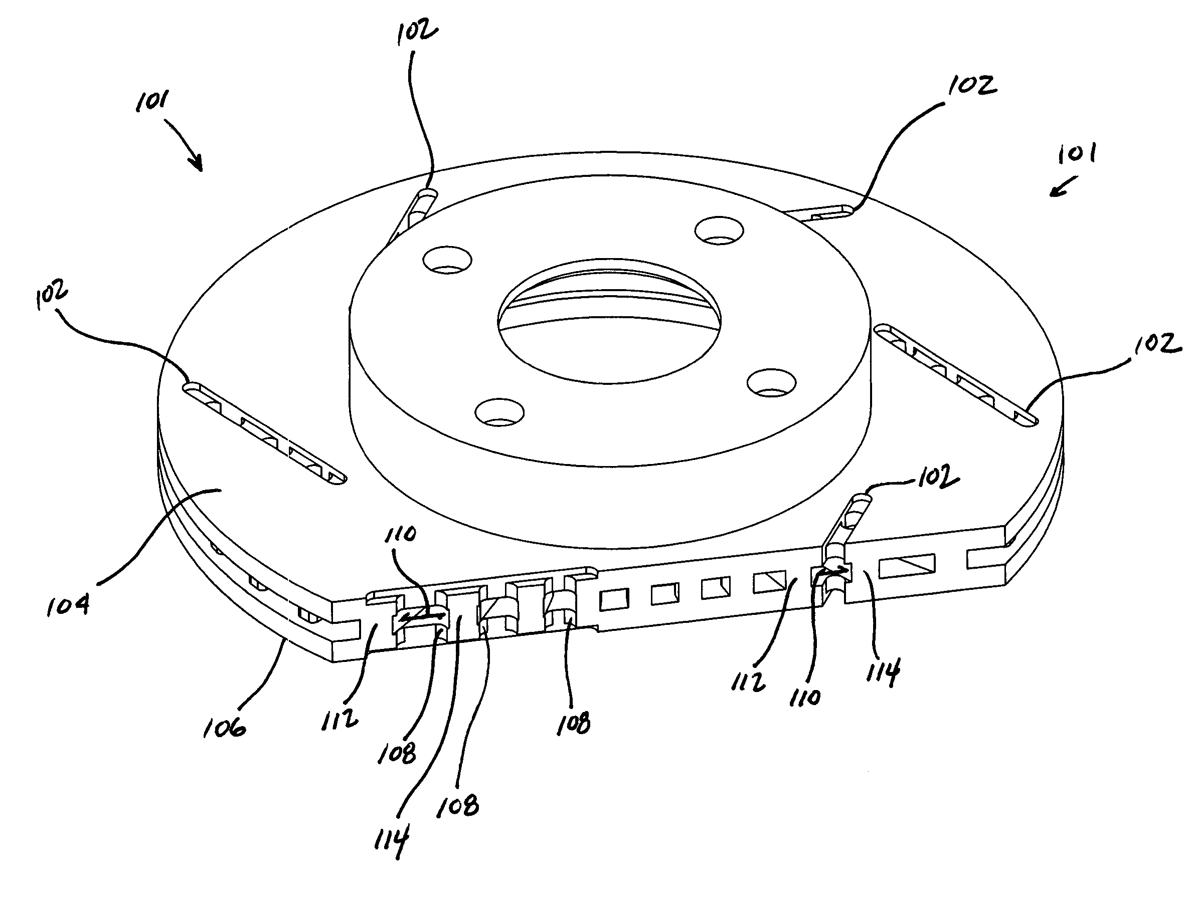
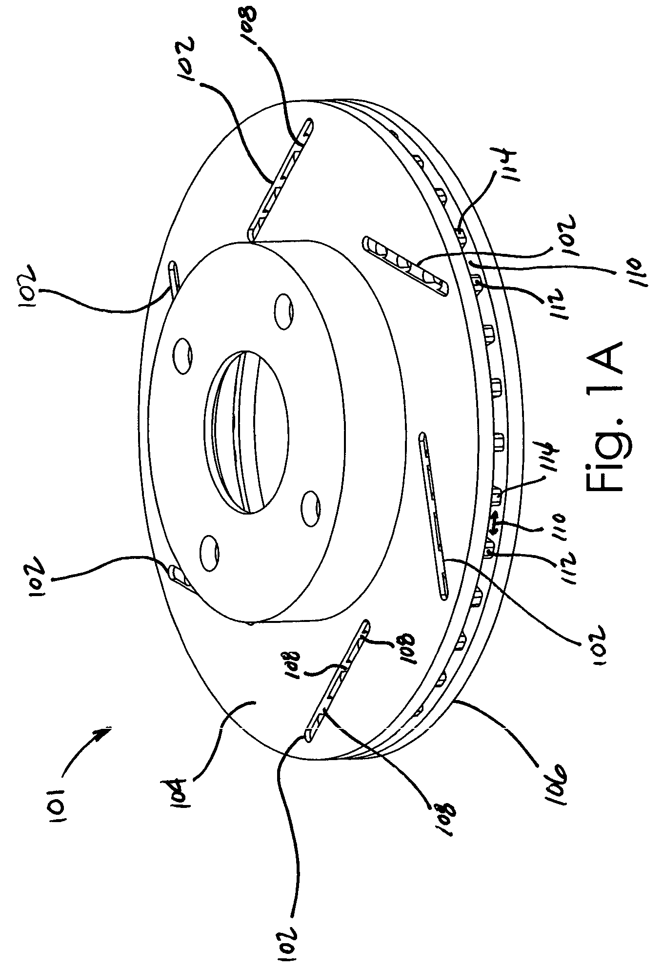
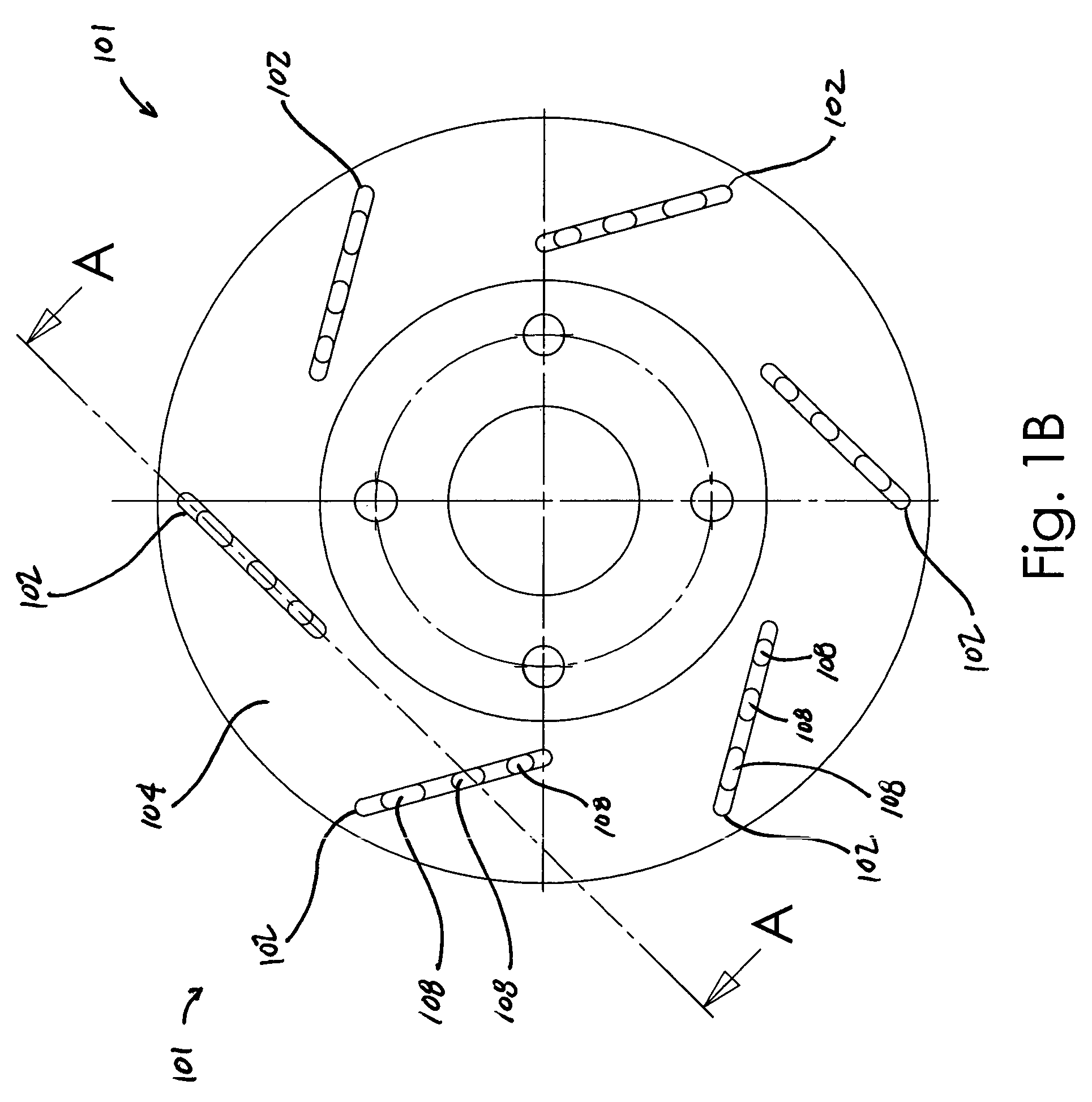
[0024]As shown in FIGS. 1A–2, a disc brake rotor 101, for example, may include a plurality of slots 102 formed into either or both external braking surfaces 104 and 106 of the disc brake rotor 101. The depth of the slots are formed at a predetermined depth. Such depths may be, for example, between 0.01″–0.50″ or greater, depending upon size of the brake rotor and braking application (passenger car, racing, bus, aircraft), or any other depth familiar to those of ordinary skill in the art for such slots. The slots may be positioned in any fashion: angled, as shown in FIG. 1, curved, zig-zag, straight, and any combination thereof.

[0025]The width of the slot may be between 0.01″ and several inches or more, depending on the size of the brake rotor and braking application. For most automotive applications (e.g., passenger cars), for example, the width may be between 0.0625″ and 0.25″. The length of the slot may be any length, but preferably such that the position of the slot on the extern...


PUM


Abstract

A brake rotor and methods for cooling and/or removing debris from a brake rotor are provided. The brake rotor may include a first and second annular braking surfaces jointly defining inner and outer circumferential surfaces and a central portion and a hat portion disposed in the central portion and adapted for mounting the rotor to a vehicle. The rotor may also include a plurality of vanes provided between the inner and outer circumferential surfaces, which may define a plurality of corresponding flow channels between at least a pair of vanes. Each flow channel may include a first flow channel opening (e.g., inlet) provided near the central region and a second flow channel opening (e.g., outlet) provided near a periphery of the brake rotor. The rotor and methods also may include a plurality of first slots provided on the first annular braking surface and a plurality of second slots provided on the second annular braking surface corresponding to the plurality of first slots. At least one first opening may be included within one or more slots. Similarly, at least one second opening may be provided within each second slot. Each second opening of each second slot may correspond substantially to and fluid communicate with a first opening of a first slot.

Description

CLAIM TO PRIORITY[0001]This application claims benefit under 35 U.S.C. § 119(e) of U.S. Provisional Patent Application No. 60 / 462,110, filed Apr. 11, 2003, the entire disclosure of which is herein incorporated by reference.FIELD OF THE PRESENT INVENTION[0002]Embodiments of the present invention are directed toward novel brake rotor designs, and more particularly to solid and vented brake rotors having a slotted, vented braking surface.BACKGROUND OF THE INVENTION[0003]Generally, existing brake rotors include solid, non-venting rotor designs and venting designs, as disclosed in U.S. Pat. No. 5,878,848 (vented). Accordingly, conventional ventilated brake rotors generally include a pair of mutually spaced-apart annular disks that present two opposed external braking surfaces for engaging brake pads under a clamping operation of a braking actuator (brake caliper). The space between the disks typically includes a number of vanes with flow passages defined between each pair of adjacent van...

Claims


Application Information

Patent Timeline
Patent Type & Authority Patents(United States)
IPC IPC(8): F16D65/12F16D65/00F16D69/00
CPCF16D65/0031F16D65/12F16D2069/004F16D2065/1328
Inventor LIN, WARREN
Owner LIN WARREN
Why Eureka
Try Eureka