Injection device providing automatic needle retraction

Active Publication Date: 2006-08-29
ALZA CORP
View PDF14 Cites 56 Cited by
  • Summary
  • Abstract
  • Description
  • Claims
  • Application Information

AI Technical Summary

Benefits of technology

[0006]The present invention includes an automatic injection device that reliably provides automatic needle retraction even when manufactured with part and assembly tolerances typical of low-cost and high-volume manufacturing processes. The injector of the present invention includes a body, a syringe cartridge, a drive mechanism, and a bias mechanism. The syringe cartridge includes a syringe capable of containing a desired medicament and an associated needle to effect injection. The drive mechanism includes an energy source, a drive member, and a compound plunger with a releasable coupling. The energy source included in the drive mechanism exerts a force against the drive member and such force is transferred to the syringe cartridge through the compound plunger, which is releasably coupled to the drive member. The transfer of force from the energy source through the drive member and compound plunger to the syringe cartridge displaces the syringe

Problems solved by technology

However, the injector designs taught in the '181, '732, and '078 patents include no feedback mechanism to ensure that the retraction mechanism decouples the plunger from the drive mechanism precisely as the plunger reaches the end of its travel.
In injection devices designed according to the '181, '732, and '078 patents, a tolerance stack-up of as little as 0.005″ away from a specified value may cause early or late actuation of the retraction mechanism.
If the retraction mechanism actuates too early, the plunger will be decoupled from the drive mechanism before the plunger has terminated its travel within the needle bearing devices, leaving an amount of medicament undelivered.
Conversely, if a tolerance stack-up causes late actuation of the retraction mechanism, th

Method used


Image

  • Injection device providing automatic needle retraction
  • Injection device providing automatic needle retraction
  • Injection device providing automatic needle retraction

Examples


Example

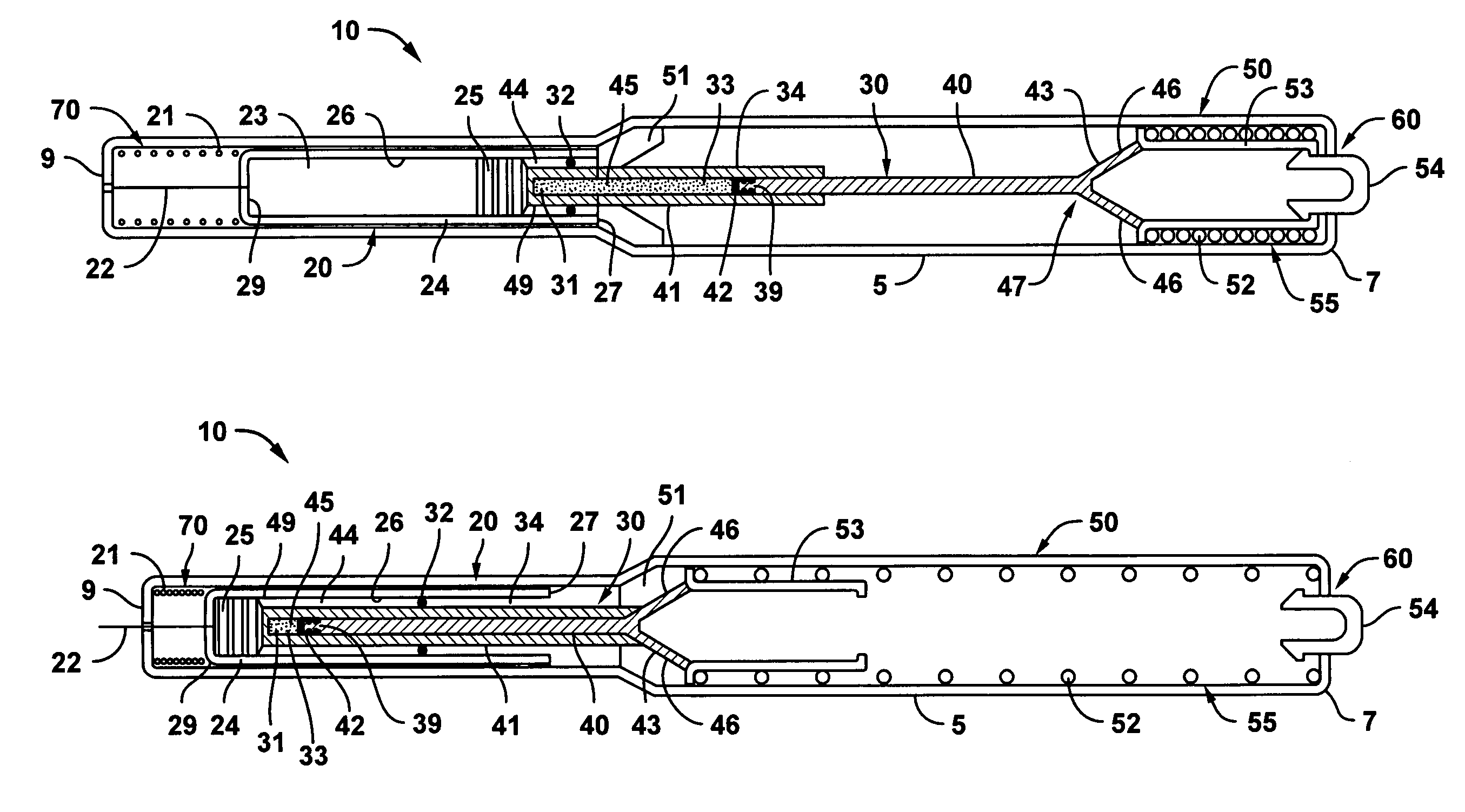
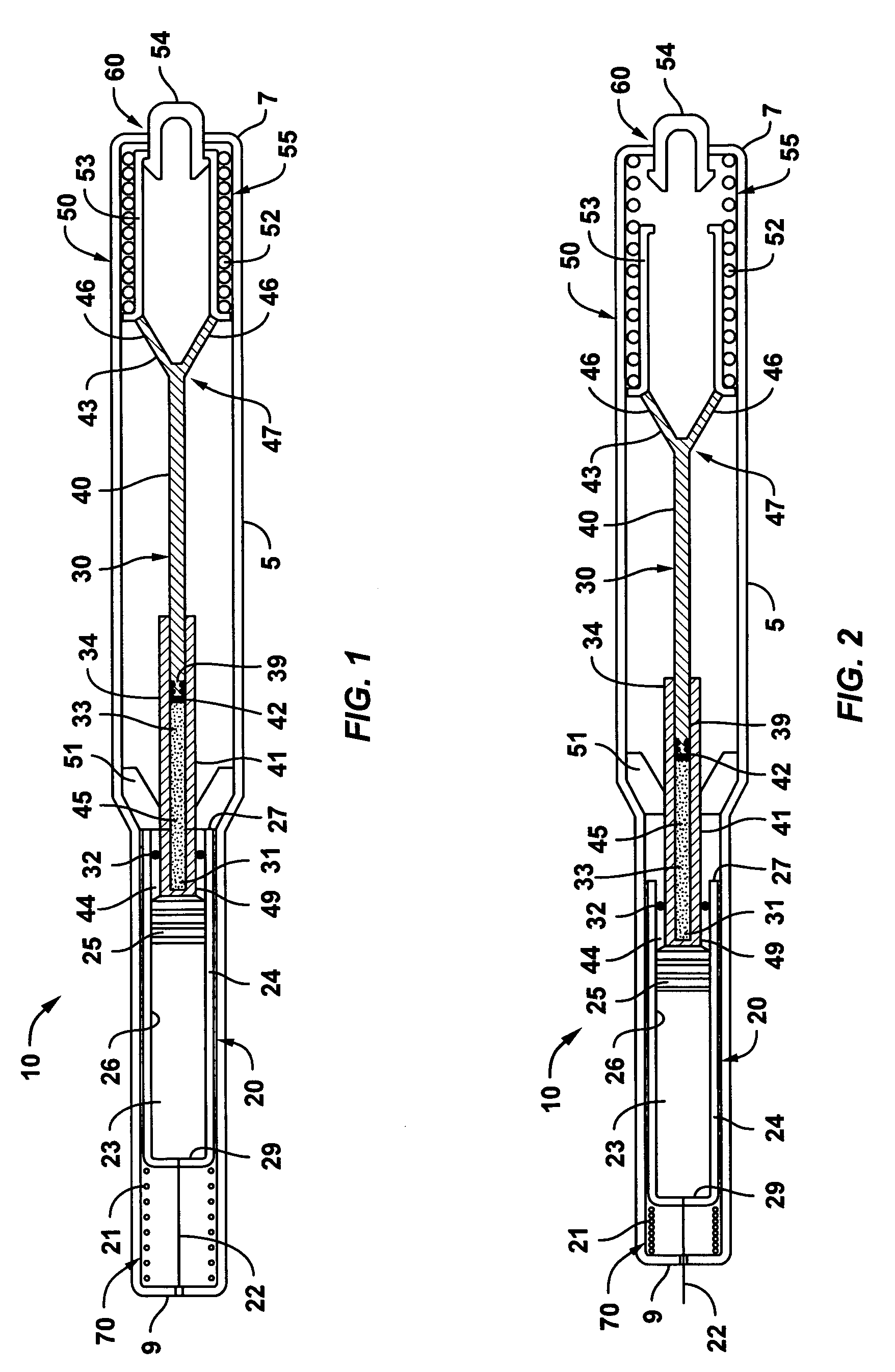
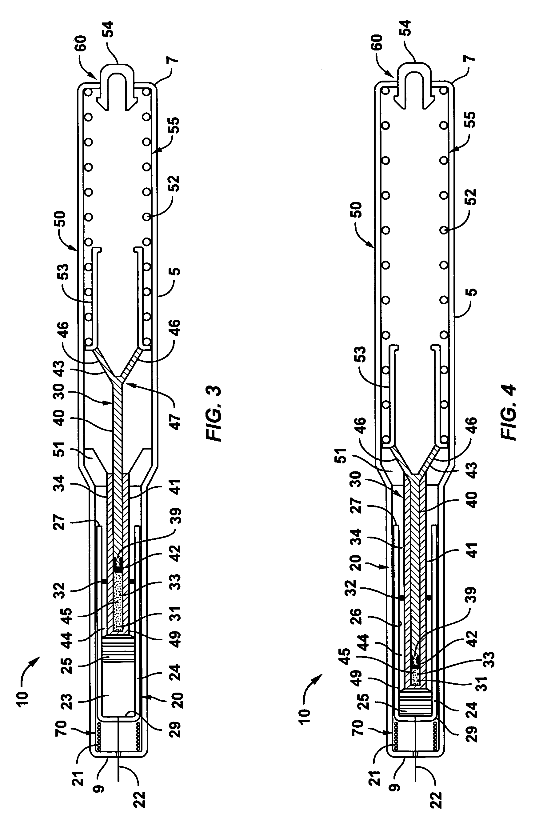
[0013]An embodiment of an injector according to the present invention is successively illustrated in FIG. 1 through FIG. 6. As can be appreciated by reference to the figures, an injector 10 according to the present invention includes a body 5 housing a syringe cartridge 20, a trigger mechanism 60, a drive mechanism 50 that utilizes a compound plunger 30, and a bias mechanism 70 for retaining the syringe cartridge 20 within the body 5 of the injector 10. The body 5 of an injector 10 of the present invention includes a proximal end 7 and a distal end 9. Though the figures included herein illustrate a body 5 that is generally cylindrical with a wider diameter at the proximal end 7 tapering to a narrower diameter at the distal end 9, the body 5 of the injector 10 of the present invention may be formed according to any size or shape capable of housing or supporting the syringe cartridge 20, the drive mechanism 50, the compound plunger 30, and the trigger mechanism 60 included in the inje...


PUM


Abstract

The present invention includes an automatic injection device that reliably provides automatic needle retraction even when manufactured with part and assembly tolerances typical of low-cost and high-volume manufacturing processes. The injector of the present invention includes a body, a syringe cartridge, a drive mechanism, and a bias mechanism. The drive mechanism includes an energy source, a drive member, and a compound plunger with a releasable coupling. Significantly, the compound plunger included in the drive mechanism is designed to ensure needle retraction occurs after the automatic injection device has delivered the desired dose of medicament. Moreover, the design of the compound plunger included in the injector of the present invention can compensate for part and assembly tolerances typical of low-cost, high volume manufacturing processes, enabling the fabrication of a low cost automatic injection device providing reliable automatic needle retraction.

Description


Claims


Application Information

Patent Timeline
IPC IPC(8): A61M37/00A61M5/20A61M5/24A61M5/32
CPCA61M5/2033A61M5/326A61M2005/206A61M5/24
Inventor GILBERT, SCOTT
Owner ALZA CORP
Why Eureka
Try Eureka