Contactless integrated circuit reader

Inactive Publication Date: 2006-08-29
INSIDE TECH
View PDF6 Cites 112 Cited by
  • Summary
  • Abstract
  • Description
  • Claims
  • Application Information

AI Technical Summary

Benefits of technology

[0009]More particularly, one object of the present invention is to provide a si

Problems solved by technology

However, these contactless terminals are capable of recording different pieces of information relating to the operations carried out, which are sometimes necessary to collect to correctly manag

Method used


Image

  • Contactless integrated circuit reader
  • Contactless integrated circuit reader
  • Contactless integrated circuit reader

Examples


Embodiment Construction

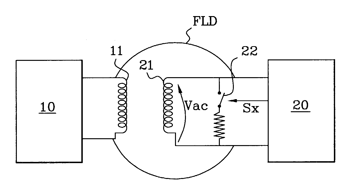
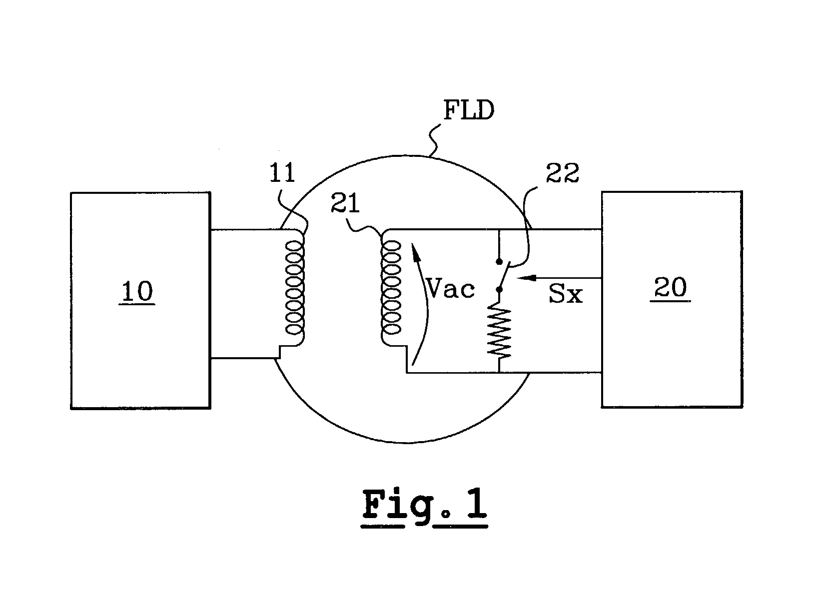
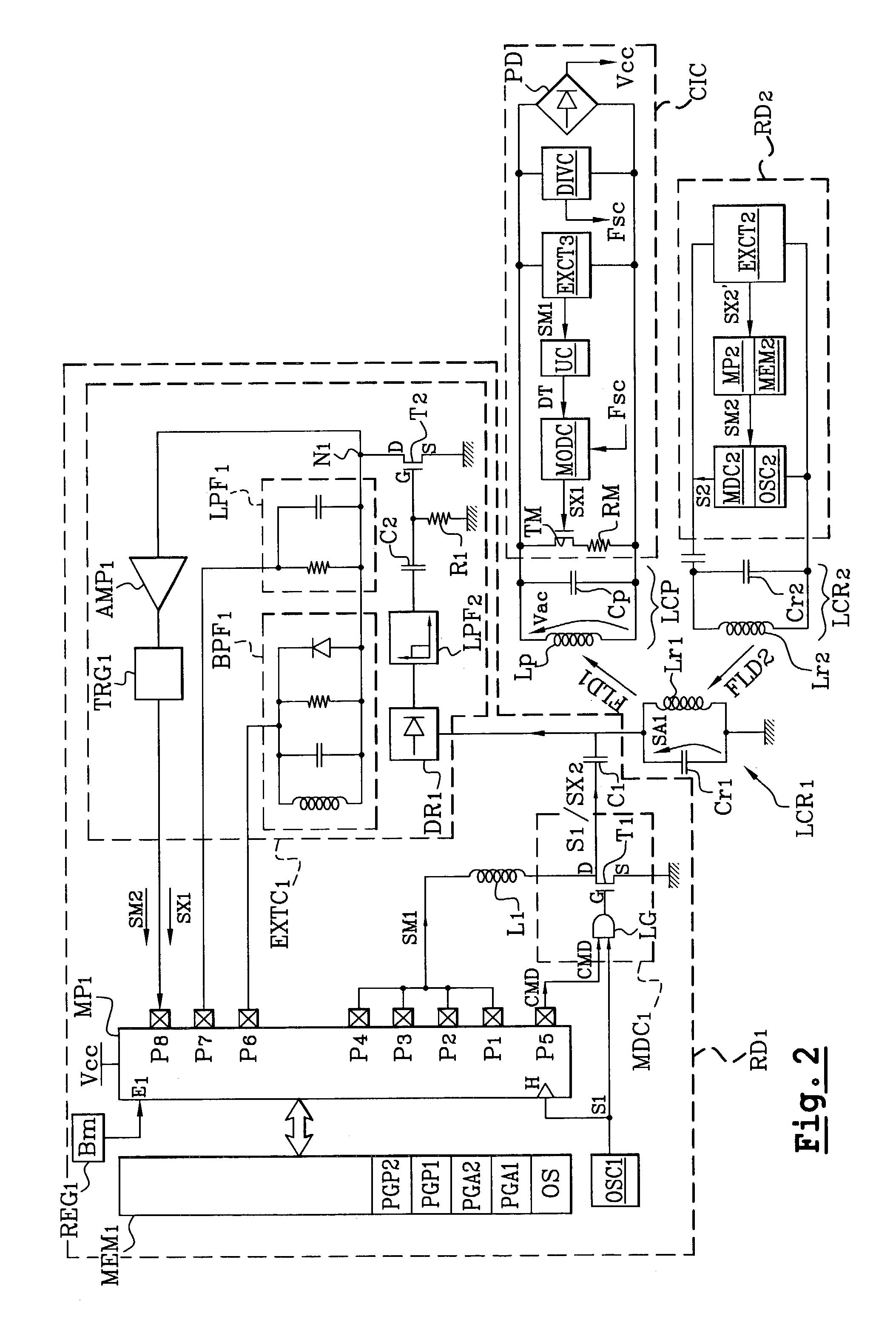
[0045]FIG. 1 is the wiring diagram of a reader RD1 according to the present invention, initially provided to exchange data with a contactless integrated circuit. Therefore, in terms of its general characteristics, the architecture of the reader RD1 is in itself well known and is described in the international applications PCT / FR00 / 00742 and PCT / FR / 00712.

[0046]The reader RD1 can be essentially distinguished from the classical reader in that it comprises means for switching to a passive operating mode in which it simulates the operation of a contactless integrated circuit to converse or communicate with another contactless integrated circuit reader.

[0047]In the following description, the reader RD1 will be described, without limitation, with reference to the standards ISO / A and ISO / B, the characteristics of which were set forth in the Background of the Invention section. Thus, the filter cut-off frequencies, the signal oscillation frequencies and the coding protocols mentioned below a...


PUM


Abstract

The present invention relates to a contactless integrated circuit reader operating by inductive coupling, comprising an antenna circuit for sending an alternating magnetic field, circuits for applying an alternating excitation signal to the antenna circuit and circuits for modulating the amplitude of an antenna signal present in the antenna circuit according to data to be sent. The reader includes circuits for simulating the operation of a contactless integrated circuit, arranged to inhibit the application of the excitation signal to the antenna circuit and to apply a load modulation signal to the antenna circuit when data is to be sent. The load modulation signal is capable of disturbing a magnetic field sent by another contactless integrated circuit reader and of being detected by the other contactless integrated circuit reader.

Description

CROSS-REFERENCE TO RELATED APPLICATIONS[0001]This application is a continuation of International Application No. PCT / FR01 / 03078, filed Oct. 5, 2001, the disclosure of which is incorporated herein by reference.BACKGROUND OF THE INVENTION[0002]The present invention relates to contactless integrated circuit readers and data transmission by inductive coupling.[0003]As represented schematically in FIG. 1, a contactless integrated circuit reader 10 operating by inductive coupling is an active system that sends an alternating magnetic field FLD by means of an antenna circuit 11 and that sends data by modulating the amplitude of the magnetic field sent. Conversely, a contactless integrated circuit 20 is a passive device that does not send a magnetic field and comprises an antenna circuit 21 comparable by analogy to the secondary winding of a transformer the primary winding of which would be constituted by the antenna circuit 11 of the reader. The magnetic field FLD sent by the reader causes...

Claims


Application Information

Patent Timeline
IPC IPC(8): H04Q5/22G06K7/00
CPCG06K7/0008
Inventor CHARRAT, BRUNOLEPRON, FRANCOIS
Owner INSIDE TECH
Why Eureka
Try Eureka