Wobble demodulator and wobble demodulation method

a demodulator and wobble technology, applied in the field of wobble demodulator and wobble demodulation method, can solve the problems of long time, degraded performance of reproducing an address, and inability to obtain the exact recording position

Active Publication Date: 2006-08-29
PANASONIC CORP
View PDF10 Cites 38 Cited by
  • Summary
  • Abstract
  • Description
  • Claims
  • Application Information

AI Technical Summary

Problems solved by technology

As a result, an exact recording position cannot be obtained when user data is recorded, and the performance of reproducing an address may be degraded.
It takes a long period of time to reproduce address information, which may degrade the access performance to the optical recording medium.

Method used


Image

  • Wobble demodulator and wobble demodulation method
  • Wobble demodulator and wobble demodulation method
  • Wobble demodulator and wobble demodulation method

Examples


embodiment 1

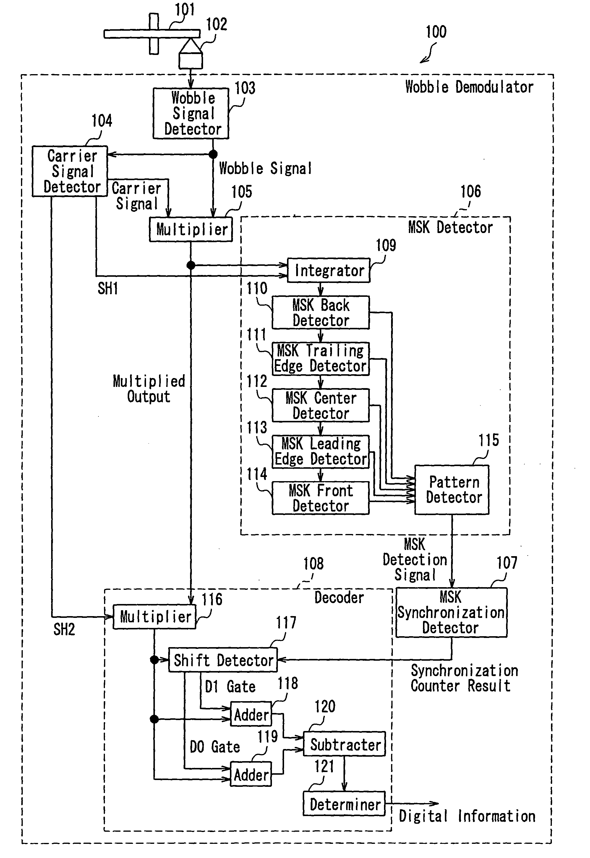
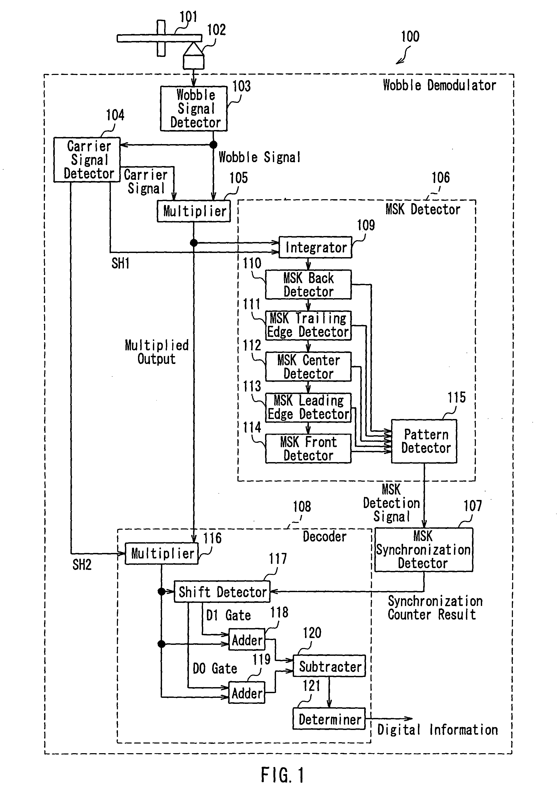
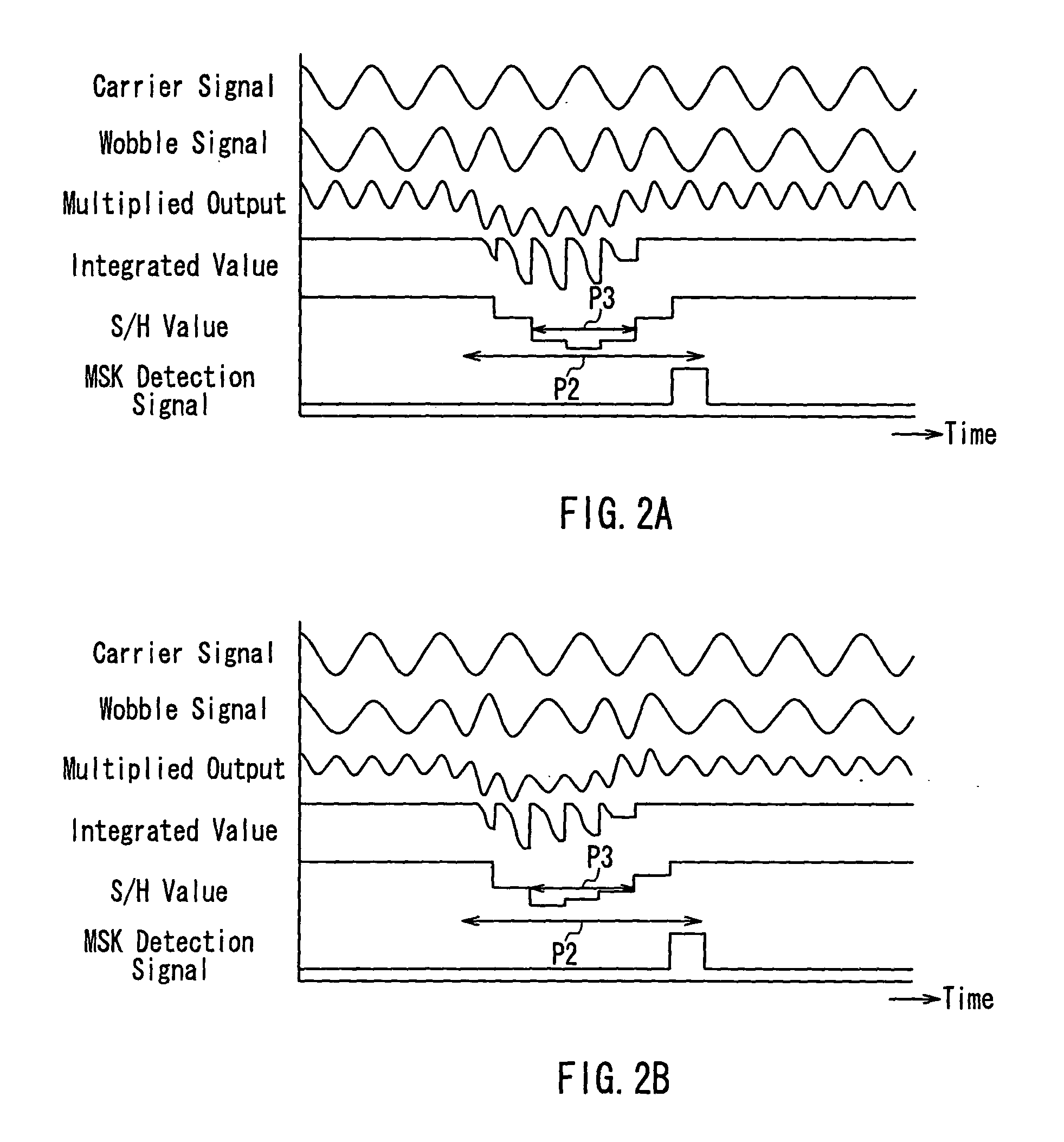
[0080]FIG. 1 is a block diagram showing a configuration of a wobble demodulator 100 according to Embodiment 1 of the present invention. In FIG. 1, reference numeral 101 denotes an optical recording medium in which a wobble track is MSK-modulated, and 102 denotes an optical head for irradiating the optical recording medium 101 with a light beam and detecting the amount of light reflected from the optical recording medium 101 to output an electric signal. Reference numeral 103 denotes a wobble signal detector for detecting a MSK-modulated wobble signal from the electric signal. Reference numeral 104 denotes a carrier signal generator for generating a carrier signal Cos (ωt) synchronized in phase with the wobble signal. Reference numeral 105 denotes a multiplier for multiplying the wobble signal by the carrier signal, and 106 denotes a MSK detector for detecting a MSK modulation mark based on a multiplied output from the multiplier 105. Reference numeral 107 denotes a MSK synchronizati...

embodiment 2

[0109]FIG. 6 is a block diagram showing a configuration of a wobble demodulator 100A according to Embodiment 2. In FIG. 6, reference numeral 1001 denotes an optical recording medium on which a MSK-modulated wobble track is formed, and 1002 denotes an optical head for irradiating the optical recording medium 1001 with a light beam and detecting the amount of light reflected from the optical recording medium 1001 to output an electric signal. Reference numeral 1003 denotes a wobble signal detector for detecting the MSK-modulated wobble signal from the electric signal. Reference numeral 1004 denotes a carrier signal generator for generating a carrier signal Cos (ωt) synchronized in phase with the wobble signal. Reference numeral 1005 denotes a multiplier for multiplying the wobble signal by the carrier signal, and 1006 denotes a MSK detector for detecting a MSK modulation mark based on a multiplied output from the multiplier 1005. Reference numeral 1007 denotes a MSK synchronization de...

embodiment 3

[0121]FIG. 8 is a block diagram showing a configuration of a wobble demodulator 100B according to Embodiment 3. In FIG. 8, reference numeral 101 denotes an optical recording medium in which a wobble track is MSK-modulated in accordance with the address formats shown in FIGS. 25 and 26. Reference numeral 102 denotes an optical head for irradiating the optical recording medium 101 with a light beam and detecting the amount of light reflected from the optical recording medium 101 to output an electric signal. Reference numeral 103 denotes a wobble signal detector for detecting the MSK-modulated wobble signal from the electric signal. Reference numeral 304 denotes a wobble PLL for generating a carrier signal synchronized in phase with the wobble signal. Reference numeral 305 denotes a PLL lock determiner for determining a synchronization state of a frequency and a phase between the wobble signal and the carrier signal. Reference numeral 306 denotes a decoder for performing MSK modulatio...


PUM

PropertyMeasurementUnit
frequencyaaaaaaaaaa
thresholdaaaaaaaaaa
threshold valueaaaaaaaaaa

Abstract

A wobble demodulator for reproducing digital information from an optical recording medium in which a track is formed in accordance with a wobble signal that is MSK-modulated so as to contain the digital information by a carrier signal with a predetermined frequency and a sine wave signal with a frequency different from that of the carrier signal, includes: a wobble signal detector for detecting a wobble signal of the track from the optical recording medium; a wobble PLL for detecting the carrier signal based on the wobble signal detected by the wobble signal detector; a multiplier for multiplying the carrier signal detected by the wobble PLL by the wobble signal detected by the wobble signal detector and outputting a multiplied output; a MSK detector for detecting a MSK modulation mark having a phase or a frequency different from that of the carrier signal, based on an integrated value obtained by integrating the multiplied output from the multiplier on a predetermined section basis; and a MSK synchronization detector for detecting a synchronization position with respect to the digital information, based on the MSK modulation mark detected by the MSK detector, wherein the MSK detector compares a continuous predetermined number of the integrated values with a first threshold value for detecting a central portion of the MSK modulation mark, a second threshold value for detecting leading and trailing edges of the MSK modulation mark, and a third threshold value for detecting non-modulated portions before and after the MSK modulation mark, and detects the MSK modulation mark based on a pattern of a comparison result.

Description

BACKGROUND OF THE INVENTION[0001]1. Field of the Invention[0002]The present invention relates to a wobble demodulator for detecting and demodulating a wobble signal from an optical recording medium, on which digital information such as address information is recorded by forming a MSK-modulated wobble in a track, thereby demodulating digital information, and a wobble demodulation method.[0003]2. Description of the Related Art[0004]Recently, the density of an optical recording medium is increasing. In general, a track groove is formed previously on a recordable optical recording medium, and information is recorded along the track groove, i.e., on the track groove or in a region (land) sandwiched by the track grooves. The track groove is formed so as to meander in a sine wave form, and information is recorded in synchronization with a dock generated based on a wobble period of the track groove. Furthermore, in order to record information at a predetermined position on a recording surfa...

Claims


Application Information

Patent Timeline
Patent Type & Authority Patents(United States)
IPC IPC(8): G11B20/08G11B15/52G11B20/10G11B20/14G11B27/19G11B27/24
CPCG11B7/0053G11B20/1403G11B27/24G11B27/19G11B2220/20G11B20/10
Inventor NAKATA, KOHEIGUSHIMA, TOYOJIUSUI, MAKOTOOHSHIMA, KAZUYAMINAMINO, JUNICHI
Owner PANASONIC CORP
Why Eureka
Try Eureka