Dynamic optimal path selection in multiple communications networks

a communication network and dynamic optimal technology, applied in the field of communication systems, can solve the problems of no longer optimal selection path, no way to exploit the availability of multiple networks in an optimal way, and no standard that describes how

Inactive Publication Date: 2006-08-29
MITSUBISHI ELECTRIC RES LAB INC
View PDF14 Cites 79 Cited by
  • Summary
  • Abstract
  • Description
  • Claims
  • Application Information

AI Technical Summary

Benefits of technology

[0023]A method and system connects a first terminal via multiple networks to a second terminal. An environment description is acquired and parsed by a description parser into cost parameters using a set of rules. An objective function evaluates t

Problems solved by technology

That system does not consider the possibility that even if there is no failure, it may be desired to switch from a working channel to the protection channel.
In general, the primary drawback of using the prior art methods is that other networks and other paths may, at a later time, better satisfy the objective function after the network and path have initially been selected.
In that case, the selected path is no long

Method used


Image

  • Dynamic optimal path selection in multiple communications networks
  • Dynamic optimal path selection in multiple communications networks
  • Dynamic optimal path selection in multiple communications networks

Examples


Embodiment Construction

Introduction

[0035]The present invention describes a system and method for dynamically selecting an optimal communication path in multiple networks. Each network may have different capacity and available bandwidth at the time of a service request. Furthermore, each network is defined by time-variant and time-independent cost parameters.

Multiple Networks

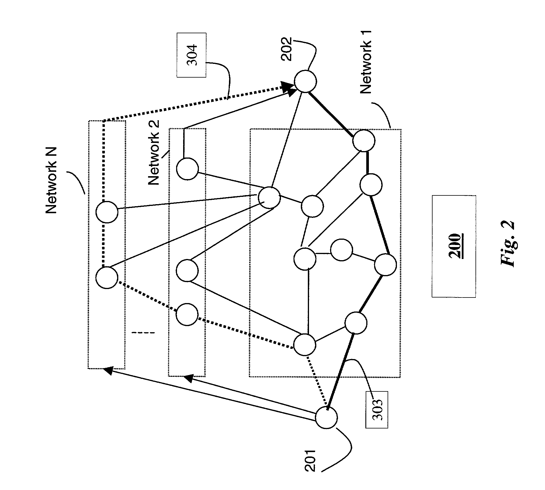
[0036]FIG. 2 shows multiple networks (Networks 1, 2, . . . , N) 200 with dynamic optimal path selection according to the invention. The optimal path connects terminals 201–202. The invention models optimal path selection with a slotted time approach, as described in greater detail below. A time slot can be independent, or dependent on traffic characteristics, or based on a temporal cost changes in all available networks. In a video application, for example, a time slot can be the duration of a single video frame, or a group of pictures (GOP).

[0037]The bold path 303 indicates the optimal path initially selected at the time the connectio...


PUM


Abstract

A method and system connects a first terminal via multiple networks to a second terminal. An environment description is acquired and parsed by a description parser into cost parameters using a set of rules. An objective function evaluates the cost parameters to determine an optimal path to connect the first terminal to the second terminal through the multiple networks using a switch. The selection of the optimal path can be done periodically during a particular application session.

Description

RELATED APPLICATION[0001]This application is related to U.S. patent application Ser. No. 10 / 078,960, filed herewith, and incorporated herein by reference.FIELD OF THE INVENTION[0002]This invention relates generally to communications systems with multiple networks and terminals that can connect to any one of the networks, and in particular to a method and system for dynamically selecting and accessing multiple networks optimally.BACKGROUND OF THE INVENTION[0003]As shown in FIG. 1, for a communications network 100, a path is defined as all physical links 101 and nodes 102 that connect two terminals 110–111. The nodes can be routers, bridges, gateways, and the like The transmission medium of the communication network 100 can be, for example, cable, fiber, wired, wireless, satellite, and the like. The terminals 110–111 can be any type of device capable of transmitting or receiving data via the network 100. For example, in a cable network, the terminal 110 can be a content or Web server,...

Claims


Application Information

Patent Timeline
IPC IPC(8): H04L12/26H04L12/28H04L12/56H04L29/06H04L29/08
CPCH04L12/5692H04L29/06H04L67/2823H04L67/306H04L67/14H04L67/18H04L67/303H04L69/329H04L67/52H04L67/565H04L9/40
Inventor SAHINOGLU, ZAFERVETRO, ANTHONY
Owner MITSUBISHI ELECTRIC RES LAB INC
Why Eureka
Try Eureka