Small mode-field fiber lens

a fiber lens and mode-field technology, applied in the field of fiber lenses, can solve the problems of limited working distance achievable, limited spot size in the prior art to achieve the required intensity distribution,

Inactive Publication Date: 2006-08-29
CORNING INC
View PDF58 Cites 28 Cited by
  • Summary
  • Abstract
  • Description
  • Claims
  • Application Information

AI Technical Summary

Benefits of technology

[0006]In another aspect, the invention relates to a fiber lens which comprises a single-mode fiber and a lens disposed at an end of the single-mode fiber, wherein a mode field diameter at a beam waist of a beam emerging from a tip of the lens is less than 10 μm and a ratio of distance from the tip of the lens to the beam waist to the mode field diameter at the beam waist is greater than 5.

Problems solved by technology

However, prior art has limitations on how small the spot size can be to achieve the required intensity distribution and limitations on the working distance achievable while controlling the spot size and intensity distribution.

Method used


Image

  • Small mode-field fiber lens
  • Small mode-field fiber lens
  • Small mode-field fiber lens

Examples


Embodiment Construction

[0020]The invention will now be described in detail with reference to a few preferred embodiments, as illustrated in the accompanying drawings. In the following description, numerous specific details are set forth in order to provide a thorough understanding of the invention. It will be apparent, however, to one of ordinary skill in the art that the invention may be practiced without some or all of these specific details. In other instances, well-known process steps and / or features have not been described in detail to avoid unnecessarily obscuring the invention. The features and advantages of the invention may be better understood with reference to the drawings and the following discussions.

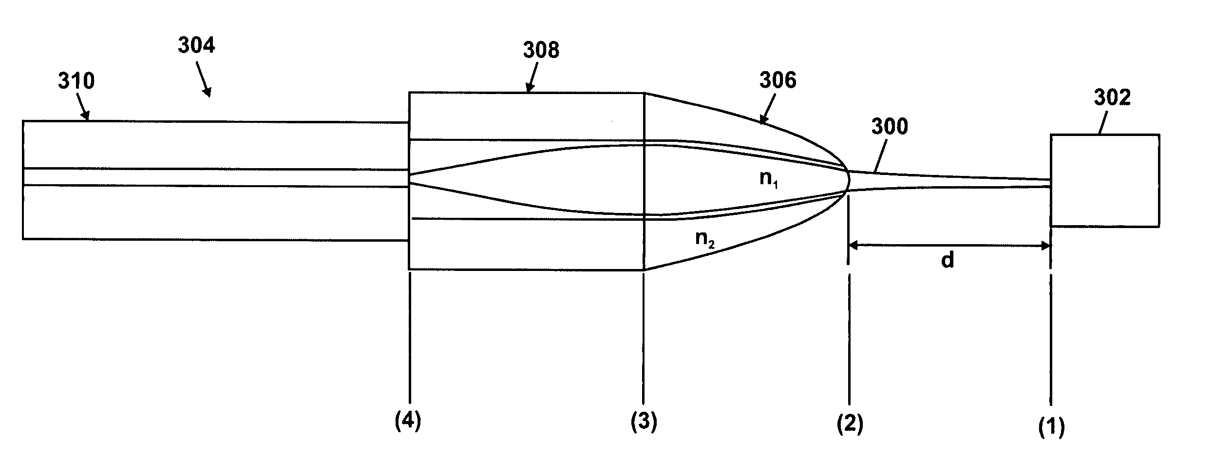
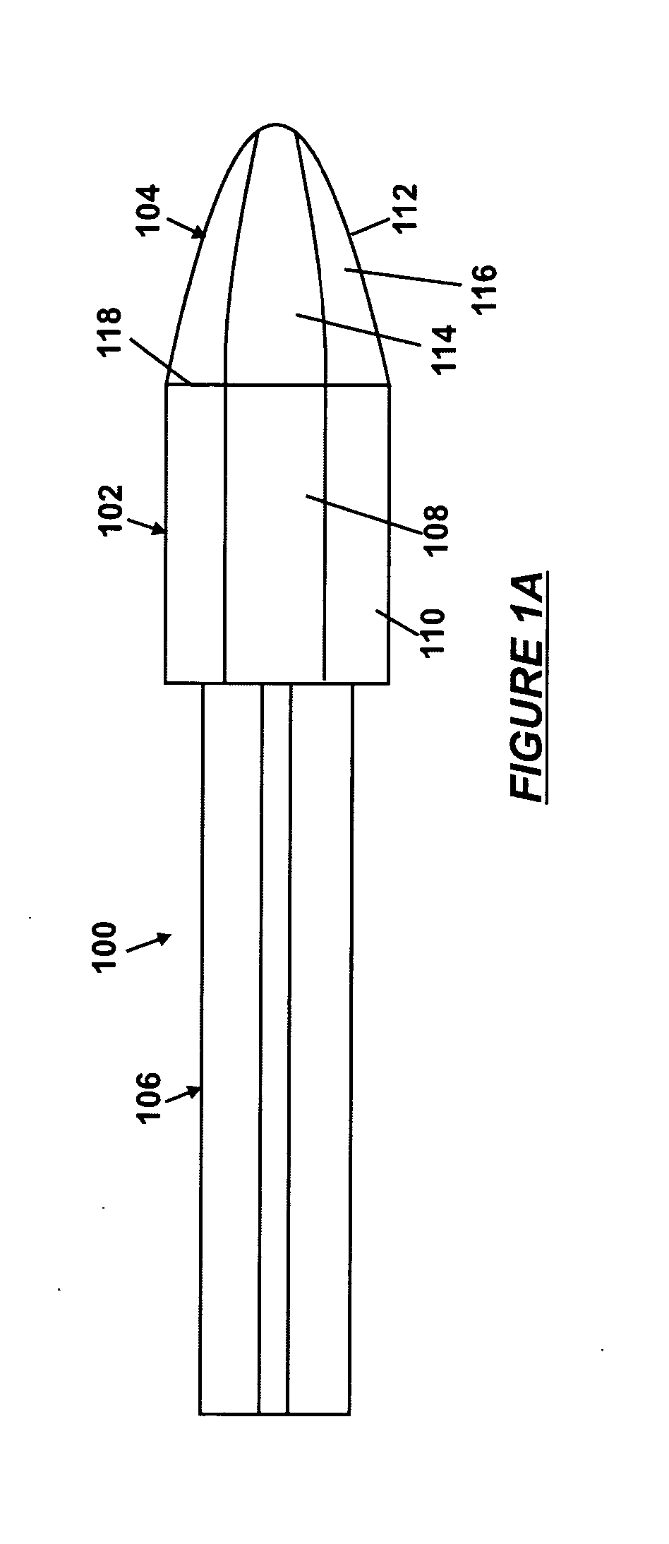
[0021]Embodiments of the invention provide a fiber lens that can focus light from an optical fiber into a spot having the required size and intensity distribution at a distance required by the application. The fiber lens uses a combination of a refractive lens and a graded-index (GRIN) lens to pr...


PUM


Abstract

A fiber lens includes a graded-index lens, a single-mode fiber disposed at a first end of the graded-index lens, and a refractive lens having a hyperbolic or near-hyperbolic shape disposed at a second end of the graded-index lens to focus a beam from the single-mode fiber to a diffraction-limited spot.

Description

CROSS-REFERENCE TO RELATED APPLICATIONS[0001]This application claims the benefit of U.S. Provisional Application Ser. No. 60 / 437,328, filed Dec. 31, 2002, entitled “Small Mode-Field Fiber Lens.”BACKGROUND OF THE INVENTION[0002]The invention relates generally to optical devices for coupling optical signals between optical components. More specifically, the invention relates to a fiber lens for coupling signals between optical components.[0003]Various approaches are used in optical communications to couple optical signals between optical components, such as optical fibers, laser diodes, and semiconductor optical amplifiers. One approach involves the use of a fiber lens, which is a monolithic device having a lens disposed at one end of a pigtail fiber. Light can enter or exit the fiber lens through either the lens or the pigtail fiber. The fiber lens can focus light from the pigtail fiber into a spot having the required size and intensity at a selected working distance. However, prior ...

Claims


Application Information

Patent Timeline
Patent Type & Authority Patents(United States)
IPC IPC(8): G02B6/32G02B6/00G02B6/255G02B6/42
CPCG02B6/2552G02B6/4206G02B6/32G02B6/4203
Inventor BHAGAVATULA, VENKATA A.HIMMELREICH, JOHNSHASHIDHAR, NAGARAJA
Owner CORNING INC
Why Eureka
Try Eureka