Sidetrack vehicle washer with rotating spray arm

a technology for washing machines and sidetrack vehicles, which is applied in the direction of vehicle exterior cleaning apparatus, cleaning process and equipment, and cleaning apparatus, etc. it can solve the problems of sprayed cleaning fluid dispersing too much before reaching the vehicle surface, requiring a large amount of floor space, and requiring a large amount of space. , to achieve the effect of accurately indicating the position and lessening the risk of catching the washing

Inactive Publication Date: 2006-09-05
SUPERIOR INVESTMENTS INC AN ARIZONA
View PDF38 Cites 16 Cited by
  • Summary
  • Abstract
  • Description
  • Claims
  • Application Information

AI Technical Summary

Benefits of technology

[0022]To aid the washing arm in sweeping around the front and rear corners of the vehicle to be washed, front end and / or rear end sensor elements can be provided for reciprocal forward and rearward movement with the gantry to sense that the gantry is disposed proximate the front end or rear end, respectively, of the vehicle to be washed.
[0026]Preferably, a washing arm motor is also provided on the movable support member and is coupled to the washing arm rotation shaft for selectively rotating the washing arm and the cam plate secured thereto. The washing arm motor rotates the washing arm to sweep the spray nozzles around a corner of the vehicle to be washed. A cam position sensor, e.g., a proximity switch, is provided for sensing that one of the four indexing grooves of the cam plate is substantially aligned with the roller or other engaging member. In that case, the washing arm motor turns off to discontinue further rotation of the washing arm. Ideally, the cam plate outer periphery has a flattened region adjacent each of the four grooves formed therein. These flattened regions allow the roller or other engaging member to be dislodged from the indexing grooves onto the corresponding adjacent flat when the washing arm motor begins each quarter turn rotation. On the other hand, these indexing grooves resist rotation of the cam plate, and hence rotation of the washing arm in the opposite direction. This feature is helpful in preventing the washing arm from being dragged against the vehicle if the washing arm strikes a side mirror or other obstruction.
[0029]Still another aspect of the present invention relates to a configuration of the vertical portion of the washing arm that allows for thorough washing of lower portions of the vehicle while lessening the risk of catching the washing arm on a projection extending from the vehicle. In this regard, the washing arm is rotatably supported for rotation about a substantially vertical rotation axis. The vertical portion of the washing arm including a lowermost section and a mid-section. The lowermost section has a first spray nozzle for directing cleaning fluid at lower portions of the vehicle to be washed, and the mid-section has a second spray nozzle for directing cleaning fluid at elevated portions of the vehicle to be washed. The first nozzle is disposed more closely to the vertical rotation axis than the second nozzle. This allows the first nozzle to be positioned relatively close to the lower portions of the vehicle, while the second spray nozzle is spaced further away to avoid contact with side view mirrors or other projections extending from the vehicle.
[0030]Yet another aspect of the present invention relates to an improved vehicle washing apparatus for accurately indexing the position of the vehicle to be washed within the washing bay. A vehicle washing bay is provided for accommodating a vehicle to be washed. The vehicle washing bay includes a longitudinal axis extending from a rear end of the washing bay to an opposing front end of the washing bay; it also includes a lateral axis extending between opposing left and right sides of the vehicle washing bay. A movable support member is adapted to be moved generally between the rear end and the front end of the washing bay for directing cleaning fluid along the vehicle to be washed. A wheel guide is disposed within the vehicle washing bay for receiving one of the front wheels of the vehicle to be washed, and for guiding the vehicle to a known position relative to the lateral axis of the washing bay. A first sensor, which might take the form of a treadle switch or pressure sensitive mat, is positioned within the washing bay at a first predetermined index point for sensing that one of the front wheels is properly positioned over (or proximate to) the first sensor. A first visual indicator, for example, an illuminated “Stop” sign, is displayed at a point where it will be visible to a driver of the vehicle. The first visual indicator is coupled to the first sensor for providing a visual indication to the driver that the front wheel of the vehicle is properly positioned at the desired index point. Preferably, a second sensor, which may again be a treadle switch or pressure sensitive mat, if desired, is positioned at a point located just beyond the desired index point. This second sensor detects that a front wheel of the vehicle is positioned over (or proximate to) the second sensor, and hence beyond the first sensor, and creates a corresponding second signal. A second visual indicator (for example, a light that illuminates to display the warning “Back Up”), visible to the driver, is coupled to the second sensor for providing a visual indication that the front wheel has advanced beyond the desired index point.

Problems solved by technology

While such drive-through washers can handle high volumes of vehicles, they are also relatively expensive and require a significant amount of space.
Known vehicle washing systems that employ overhead carriages supported by a floor-mounted frame surrounding the washing bay often require significant floor space.
Otherwise, the sprayed cleaning fluid disperses too much before reaching the vehicle surface, and is not as effective in removing dirt and grime.
Vehicles can vary greatly in width, and it is a challenge to accommodate vehicles having a range of widths while still maintaining the spray nozzles closely proximate to the vehicle surface for effective cleaning.
On occasion, a spray washing arm will inadvertently contact a projecting portion of a vehicle.
However, the lay driver often has difficulty detecting whether the vehicle wheel has registered with the depressed trough or not.
In these instances, the vehicle may not be pulled into the bay far enough, or it might be pulled too far into the washing bay.
Apart from ensuring that the front end of the vehicle to be washed is properly indexed in the washing bay, additional difficulties arise by reason of different vehicles having different lengths.
On the other hand, assuming that the length of travel of a rollover washing apparatus in the forward / backward direction is fixed at some average length, then the washing arm will not be positioned close enough to the rear surfaces of shorter-than-average cars, and the washing arm may be positioned too close too, and actually impact, the rear surfaces of longer-than-average vehicles.

Method used


Image

  • Sidetrack vehicle washer with rotating spray arm
  • Sidetrack vehicle washer with rotating spray arm
  • Sidetrack vehicle washer with rotating spray arm

Examples


Embodiment Construction

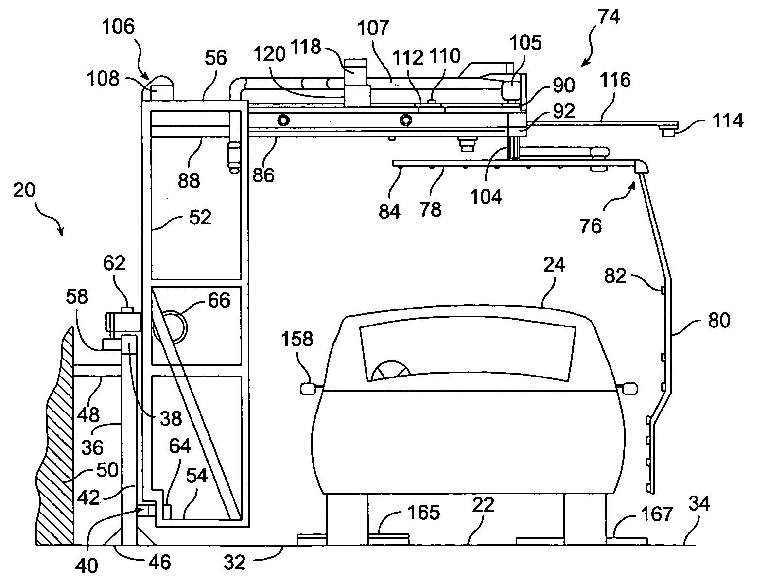
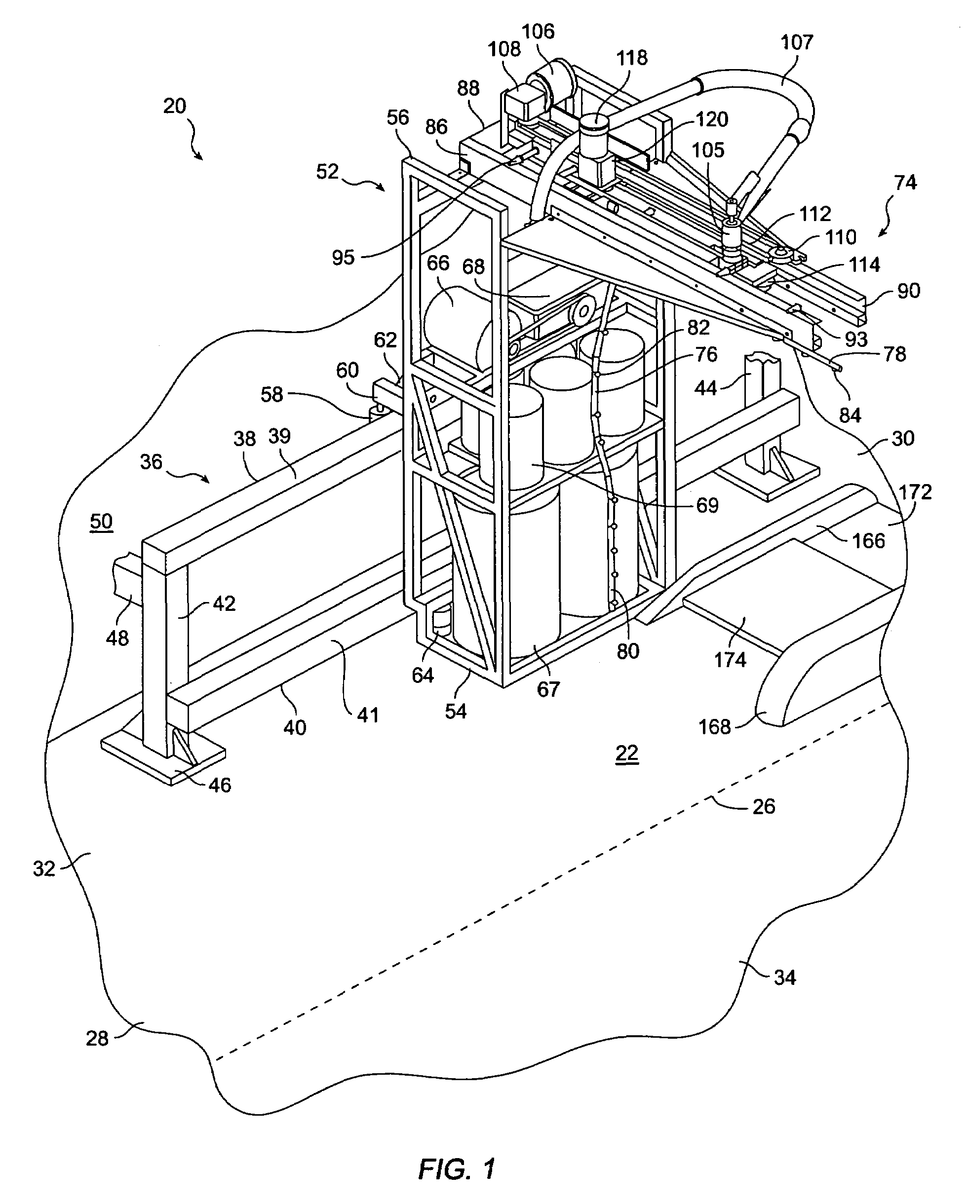
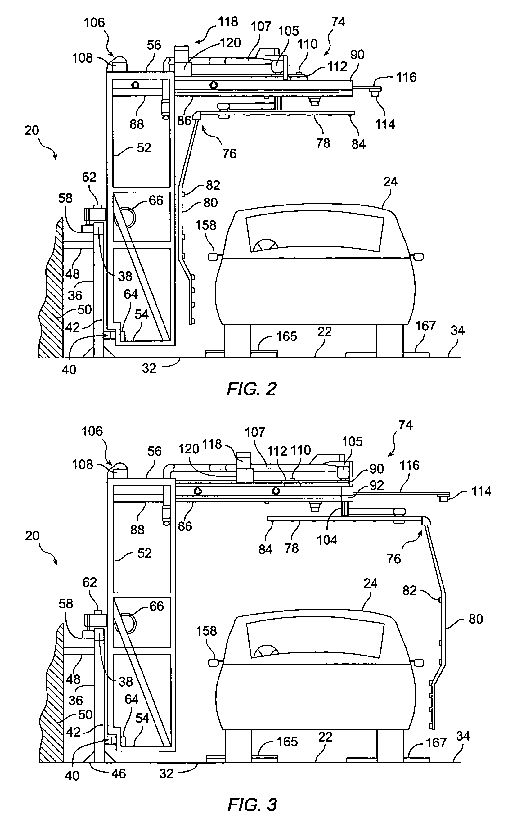
[0044]A vehicle washing apparatus incorporating a preferred embodiment of the present invention is shown in FIGS. 1–3, and is designated generally by reference numeral 20. Vehicle washer 20 includes a vehicle washing bay 22 for accommodating a vehicle 24 to be washed.

[0045]Washing bay 22 extends along a longitudinal axis (indicated by dashed line 26 in FIG. 1) between a rear end 28 and an opposing front end 30. Laterally, washing bay 22 extends between a left, or driver's side, 32 and an opposing right side 34. While not shown, washing bay 22 also has a lateral axis extending between left side 32 and right side 34 of washing bay 22, perpendicular to longitudinal axis 26.

[0046]A side track 36 extends along left side 32 of washing bay 22. While side track 36 is shown in the drawings as extending along left side 32, side track 36 could alternatively be installed to extend along right side 34 of washing bay 22. In either case, side track 36 need be installed along only one side of washi...


PUM


Abstract

A vehicle washing apparatus includes a side track extending along a washing bay. A gantry is supported for reciprocal motion along the side track by a gantry motor. Sensors detect the front and rear ends of the vehicle to control movement of the gantry. A retractable carriage extends from the gantry across the washing bay under the control of a carriage motor and a vehicle width sensor. The carriage rotatably supports a spray bar for discharging cleaning fluid. A motor rotates the spray bar to sweep around corners of the vehicle. A cam plate and engagement roller index the spray bar orientation, while limiting spray bar rotation to a single direction. A wheel guide receives the front left vehicle wheel. Treadle switches in the wheel guide, in conjunction with an illuminated display, indicate to the user when the vehicle is properly indexed in the washing bay.

Description

BACKGROUND OF THE INVENTION[0001]1. Field of the Invention[0002]The present invention relates generally to vehicle washing apparatus, and more particularly to vehicle washing apparatus wherein the vehicle to be washed is temporarily parked within a washing bay during cleaning operations.[0003]2. Description of the Related Art[0004]High volume vehicle washers typically move the vehicles to be washed past fixed-location washing devices. The vehicles to be washed are either slowly driven through such equipment, or are towed through such equipment by conveyor systems. While such drive-through washers can handle high volumes of vehicles, they are also relatively expensive and require a significant amount of space.[0005]Less-expensive “rollover” vehicle washers are also known in the art wherein an archway, or bridge structure, rolls back and forth over the vehicle to be washed. In some cases, such rollover vehicle washers roll along a pair of spaced floor rails that extend along opposing ...

Claims


Application Information

Patent Timeline
Patent Type & Authority Patents(United States)
IPC IPC(8): B08B3/02B60S3/04
CPCB60S3/04
Inventor JOHNSON, ARCHIE L.
Owner SUPERIOR INVESTMENTS INC AN ARIZONA
Why Eureka
Try Eureka