Apparatus and methods for variable furnace control

a variable furnace and apparatus technology, applied in the field of gas furnaces, can solve the problems of inability to sense the pressure level of the inducer blower, the inability to provide information to the multi-stage system, and the inability to adjust the air pressure and gas input to the combustion chamber. to achieve the optimal air-to-gas ratio of combustion, the inability to adjust the air pressure and gas input to the combustion chamber is not always accura

Inactive Publication Date: 2006-09-05
COPELAND COMFORT CONTROL LP
View PDF9 Cites 85 Cited by
  • Summary
  • Abstract
  • Description
  • Claims
  • Application Information

AI Technical Summary

Benefits of technology

[0006]The above-described furnace control system makes it possible to vary the speed of an inducer blower motor directly and precisely, so that the blower maintains a pressure drop across the combustion chamber that is optimal for the selected gas flow rate. The above-described furnace control system can be used in multi-stage and modulating furnace systems. The control system can be used not only in furnace systems that utilize electronically modulating gas valves, but also in furnace systems utilizing pressure-assist modulating gas valves.

Problems solved by technology

However, other than indicating that a specific switch trigger pressure has been reached, a pressure switch does not provide the multi-stage system with information as to actual magnitudes of blower pressure on either side of the trigger value.
Like multi-stage systems, modulating systems typically vary combustion levels based on trigger values for several pressure switches, but otherwise cannot sense inducer blower pressure levels.
Such imprecise adjustments to air pressure and gas input to the combustion chamber do not always provide optimal air-to-gas ratios for combustion.

Method used


Image

  • Apparatus and methods for variable furnace control
  • Apparatus and methods for variable furnace control
  • Apparatus and methods for variable furnace control

Examples


Embodiment Construction

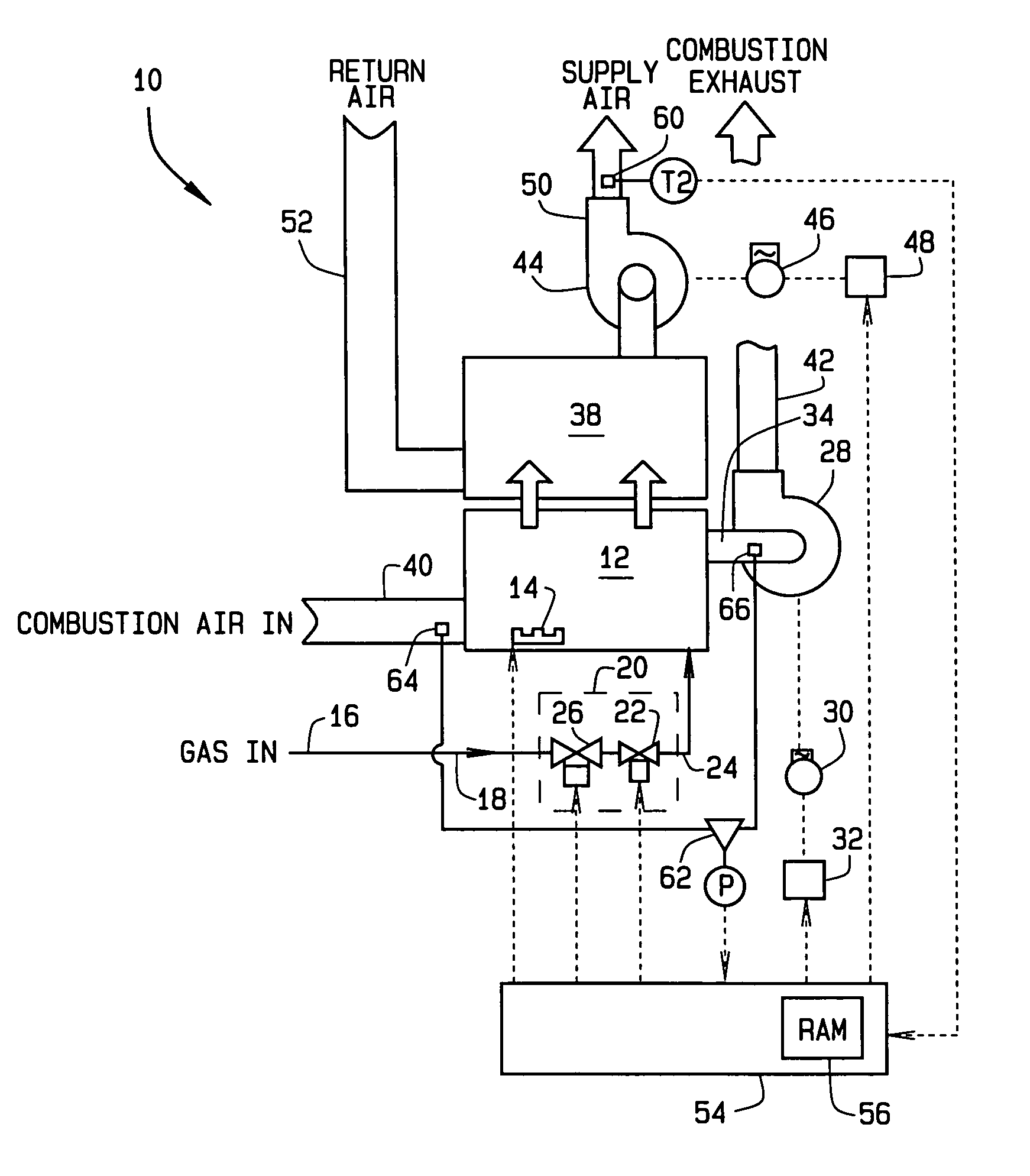
[0025]A variable modulating furnace system according to one embodiment of the present invention is indicated generally by reference number 10 in FIG. 1. The system 10 includes a combustion chamber or burner box 12 having a burner 14 therein. Gas enters a gas inlet 16 and flows through a flow path 18 to the burner box 12. An electronic modulating gas valve 20 in the gas flow path 18 controls the flow of gas to the burner 14. The gas valve 20 includes a main valve 22 in the flow path 18 adjacent an outlet 24 of the gas valve. A safety or shutoff valve 26 is disposed in the flow path 18 between the inlet 16 and the main valve 22.

[0026]An inducer blower 28 is driven by a motor 30 under control of a variable-frequency drive 32. The blower 28 is connected to the burner box 12 via a blower inlet 34. The blower 28 draws hot combustion gases from the burner box 12 to a heat exchanger 38, thereby drawing combustion air through an air inlet 40 into the burner box 12. Combustion exhaust leaves ...


PUM


Abstract

A furnace control system for controlling a gas-fired induced-draft furnace having a variable speed inducer blower. A control apparatus, responsive to a signal corresponding to the magnitude of a pressure difference between an inlet and outlet of the combustion chamber, controls blower motor speed to maintain the pressure difference at a predetermined magnitude corresponding to a selected gas flow rate. Inducer blower motor speed is varied directly and precisely to maintain an optimal pressure drop across the combustion chamber. The control system can be used in multi-stage and modulating furnace systems and in furnace systems utilizing pressure-assist modulating gas valves.

Description

FIELD OF INVENTION[0001]This invention relates generally to gas furnaces and, more particularly, to variable furnace control in multi-stage and modulating furnace systems.BACKGROUND OF THE INVENTION[0002]In an induced-draft gas furnace, a gas valve typically establishes the flow of gas into a combustion chamber while a motor-controlled blower induces air and combustion gases through the combustion chamber. Variable draft-induced gas furnaces are generally of two types: multi-stage systems and modulating systems. In a typical multi-stage system, the blower motor has several fixed speeds and the gas valve has several fixed outlet pressures. When the user of a multi-stage system selects a thermostat setting, the system signals the gas valve to supply gas to the combustion chamber at a fixed rate corresponding to the selected thermostat setting. The system also signals the blower motor to induce a draft through the combustion chamber at a fixed rate corresponding to the gas flow rate.[0...

Claims


Application Information

Patent Timeline
Patent Type & Authority Patents(United States)
IPC IPC(8): F23N1/00F24H3/00F23N3/08F23N5/18
CPCF23N3/08F23N5/18F23N2035/18F23N2033/08F23N2035/14F23N2025/04F23N2225/04F23N2233/08F23N2235/14F23N2235/18
Inventor JAESCHKE, HORST ERIC
Owner COPELAND COMFORT CONTROL LP
Why Eureka
Try Eureka