Female terminal fitting

a terminal fitting and female technology, applied in the direction of coupling device details, coupling device connection, coupling contact member, etc., can solve the problem of high production cost, and achieve the effect of preventing or reducing the opening deformation of the main portion from bending edges, preventing or reducing the opening deformation of the main portion, and improving formation efficiency

Inactive Publication Date: 2006-09-05
SUMITOMO WIRING SYST LTD
View PDF8 Cites 12 Cited by
  • Summary
  • Abstract
  • Description
  • Claims
  • Application Information

AI Technical Summary

Benefits of technology

[0009]The resilient contact is pressed by the male tab and is deformed resiliently towards the bottom wall as the male tab is inserted into the main portion. However, the catch of the protection wall is engageable with the catchable portion of the main portion. Thus, the main portion is kept substantially in a box shape and opening deformations of the main portion from bending edges can be prevented or reduced.
[0010]The catch preferably projects sideways from each of the substantially opposite side edges of the leading end of the protection wall with respect to the standing direction. The catchable portion preferably is formed by cutting off or recessing each of the substantially opposite side edges of the front end of the main portion so as to be engageable with the corresponding catch by receiving the catch from the front. Thus, the catches engage the catchable portions at positions as close as possible to the bending edges, which are supporting points of opening movements of the main portion. Thus, the catches securely prevent the opening deformations of the main portion from the bending edges. Further, the locking construction realized by the catches and the catchable portions can be formed as the protection wall is formed, and formation efficiency is better due to easy assembling.
[0012]The male tab contacts the contact portion and presses the resilient contact towards the bottom wall. However, the catches are engaged with the catchable portions at a position near a point of action of force accompanying the insertion of the male tab. Thus, a better effect of keeping the main portion in box shape can be expected.
[0014]Engaging holes are formed in side walls of the main portion. Engaging pieces are formed on the resilient contact and are loosely fittable in the engaging holes to prevent an excessive deformation of the resilient contact.

Problems solved by technology

This double wall design would lead to a higher production cost, and hence is undesirable.

Method used


Image

  • Female terminal fitting
  • Female terminal fitting
  • Female terminal fitting

Examples


Embodiment Construction

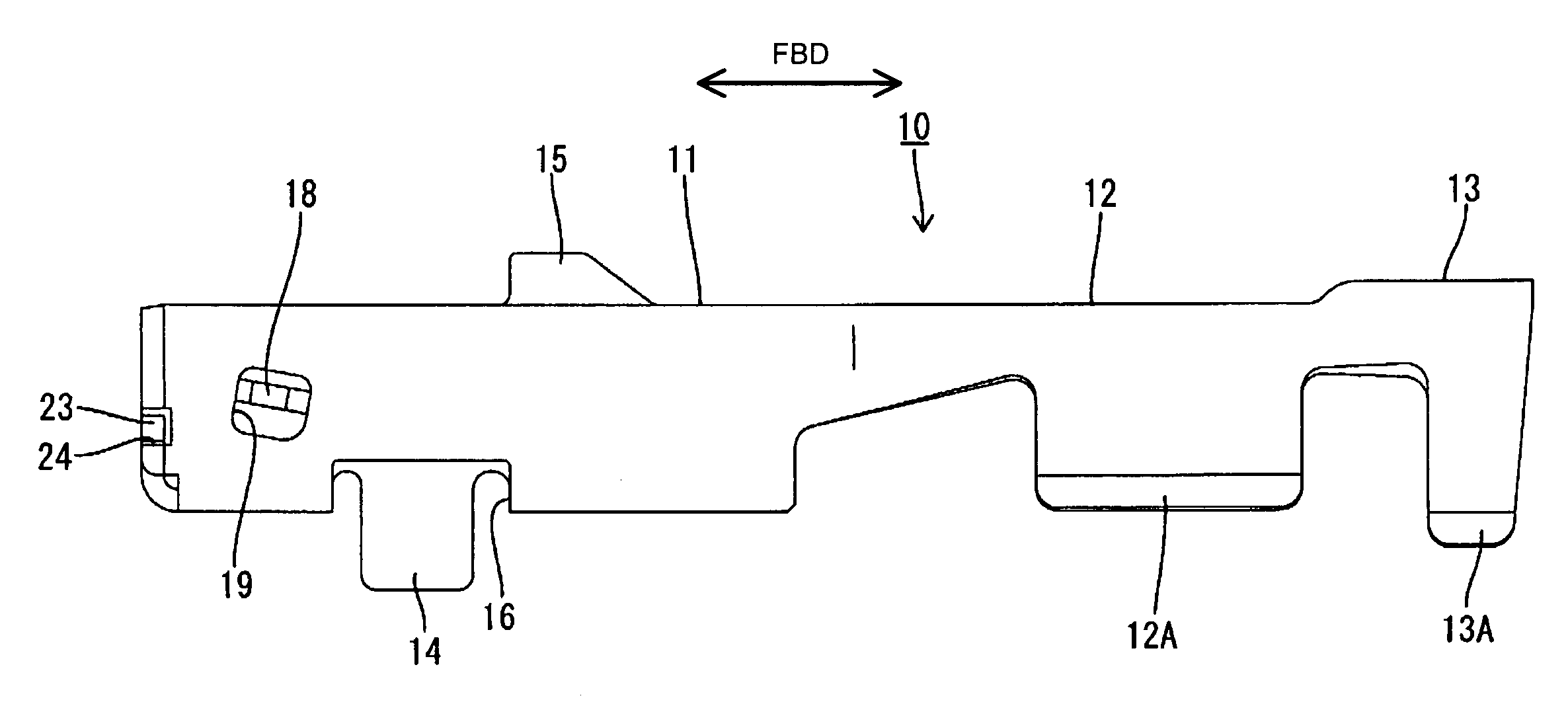
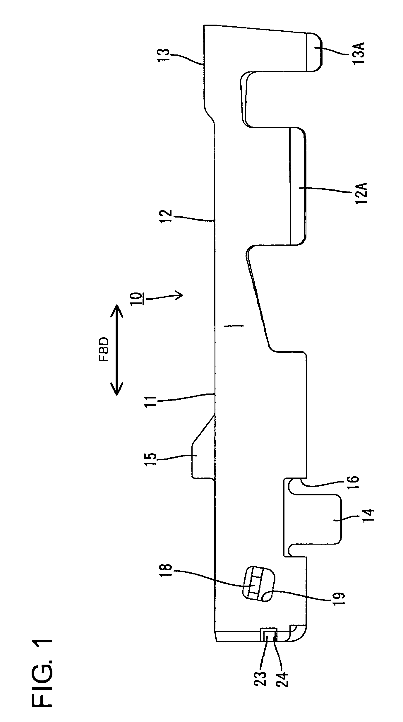
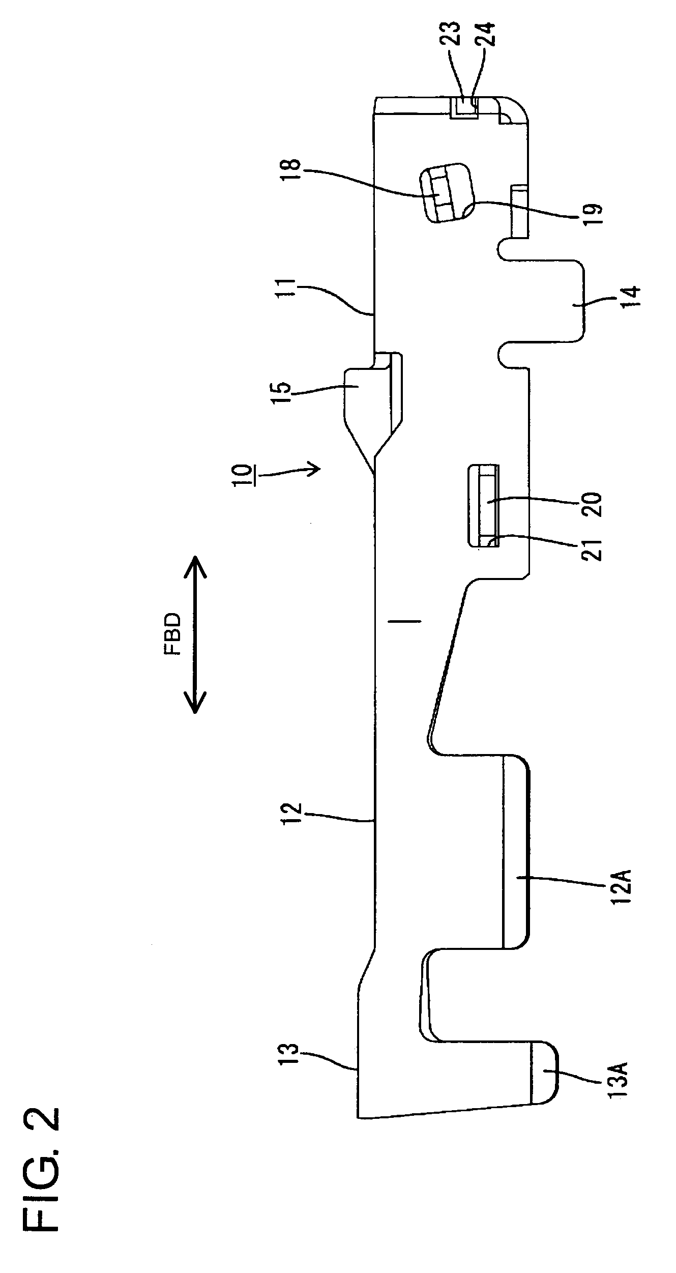
[0027]A female terminal fitting according to the invention is identified by the numeral 10 in FIGS. 1 to 7. The female terminal fitting 10 is formed by stamping or cutting an electrically conductive metallic plate, as shown in FIG. 5, and then bending, folding and / or embossing the plate. The finished female terminal fitting 10 is narrow and long along forward and backward directions FBD. In this regard, the forward and backward directions FBD refers to inserting and withdrawing directions of the female terminal fitting 10.

[0028]The female terminal fitting 10 is of unitary construction and has opposite front and rear ends. A main portion 11 is formed at the front end and is configured to receive a male tab of a mating male terminal fitting. A wire barrel portion 12 is formed behind the main portion 11 and is configured to be crimped, folded or bent into connection with an end of a core of an unillustrated insulated wire. An insulation barrel 13 is behind the wire barrel 12 at the rea...


PUM


Abstract

A female terminal fitting (10) has a box-shaped main portion (11) with an open front end. A resilient contact piece (17) is formed in the main portion (11) for resiliently contacting a mating male tab (30). A protection wall (22) extends continuously from a bottom wall (11C) before a resilient contact piece (17) while leaving a clearance for entry of the male tab (30). Catches (23) are provided at the opposite side edges of the protection wall (22) and engage with catchable portions (24) at the side edges of the front end of the main portion (11) for resisting opening forces on the main portion (11).

Description

BACKGROUND OF THE INVENTION[0001]1. Field of the Invention[0002]The invention relates to a female terminal fitting with a resilient contact piece.[0003]2. Description of the Related Art[0004]Japanese Unexamined Patent Publication No. 2000-133355 and FIGS. 8 and 9 relate to a female terminal fitting. With reference to FIGS. 8 and 9, the female terminal fitting is formed by bending a metallic plate that has been stamped into a specified development. The female terminal fitting has a rectangular tube 1 with a bottom wall 2. A mating male tab 3 can be inserted into the main portion 1 and engages a resilient contact 4 that extends obliquely forward a base portion 5 at the rear end of the bottom wall 2. A fold 4A is folded from an intermediate portion of the resilient contact 4 and is turned toward the bottom wall 2. A leg 4B extends continuously in a returning direction from the fold 4A and is held in contact with the bottom wall 2. A protuberance 4E is provided near the fold 4A and can ...

Claims


Application Information

Patent Timeline
Patent Type & Authority Patents(United States)
IPC IPC(8): H01R11/22H01R13/11H01R4/18H01R13/05H01R13/115H01R13/187
CPCH01R13/11H01R4/185
Inventor MAEDA, TAISAKU
Owner SUMITOMO WIRING SYST LTD
Why Eureka
Try Eureka