
Generic motor control system and method

a technology of motor control and control circuit, applied in the direction of motor/generator/converter stopper, dynamo-electric converter control, multiple dynamo-motor starters, etc., can solve the problems of increasing manufacturing, engineering design, parts, inventory and labor costs, and no ‘universal’ motor control circuit or module is availabl

Inactive Publication Date: 2006-09-05
BLACK & DECKER INC
View PDF30 Cites 91 Cited by
  • Summary
  • Abstract
  • Description
  • Claims
  • Application Information

AI Technical Summary

Problems solved by technology

The requirement of different dedicated control circuitry for different motors and different applications greatly increases manufacturing, engineering design, parts, inventory and labor costs.
This is because, up until the present time, no one ‘universal’ motor control circuit or module was available that could be easily tailored to meet the operational needs of different types of applications (e.g. drills, saws, grinders, etc.).

Method used


Image

  • Generic motor control system and method
  • Generic motor control system and method
  • Generic motor control system and method

Examples


Embodiment Construction

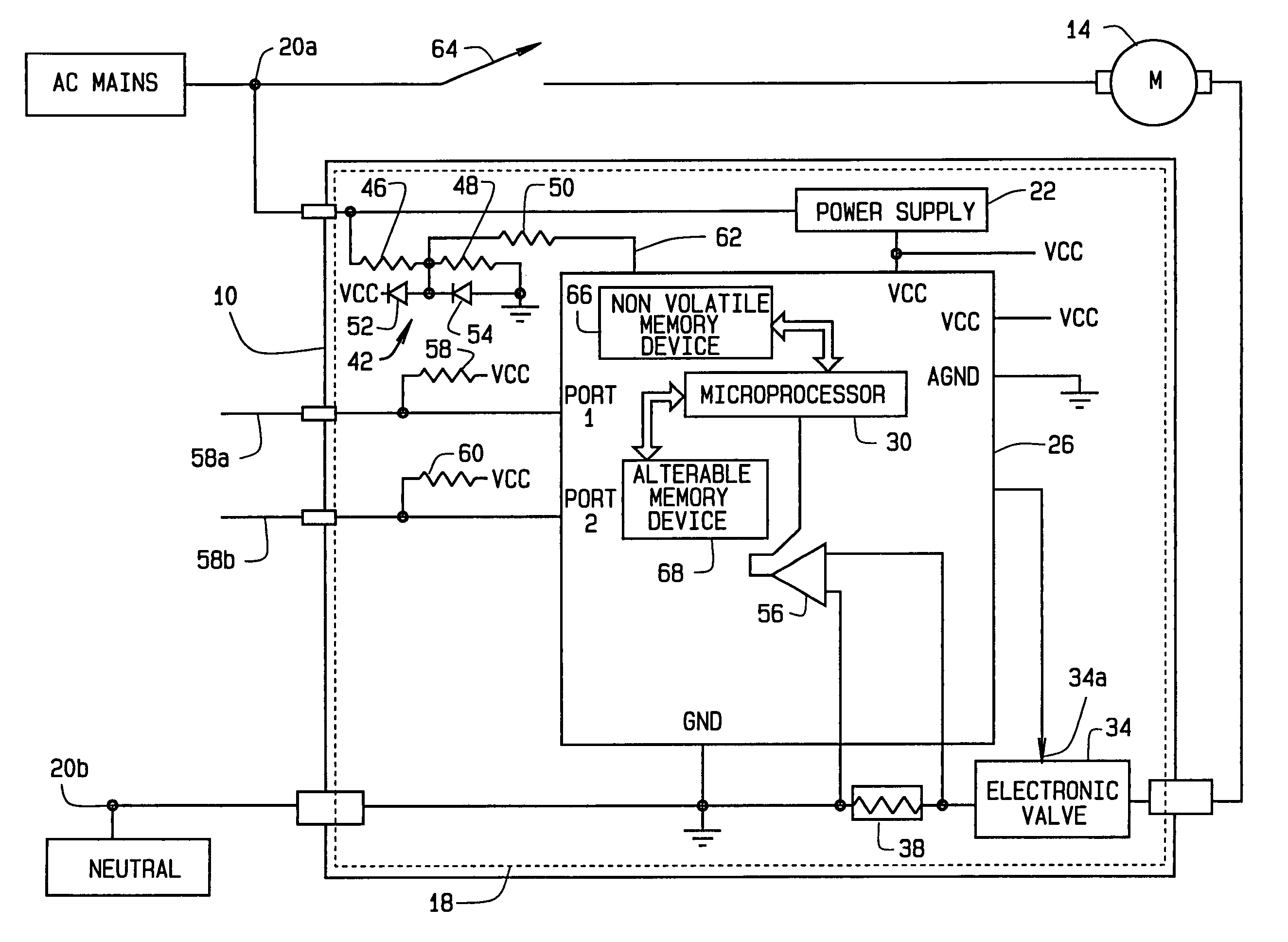
[0009]FIG. 1 is a simplified circuit diagram of a universal motor control module 10, in accordance with one preferred embodiment of the present invention. The universal motor control module 10 is connectable to an AC motor 14 that can be any one of a plurality of motors used in any one of a plurality of applications. The universal motor control module 10 is capable of controlling any of the plurality of motors, such as motor 14, in any of the plurality of motor applications. Additionally, the universal motor control module 10 includes a digital control circuit, generally indicated at 18. Therefore, the universal motor control module 10 is a digital control module that can be used to control any of the plurality of motors, in any of the plurality of applications, without altering components, component values, and / or control software to create an application specific control or control behavior.

[0010]For example, the universal module 10 can be used to control the motor of a heavy duty...


PUM


Abstract

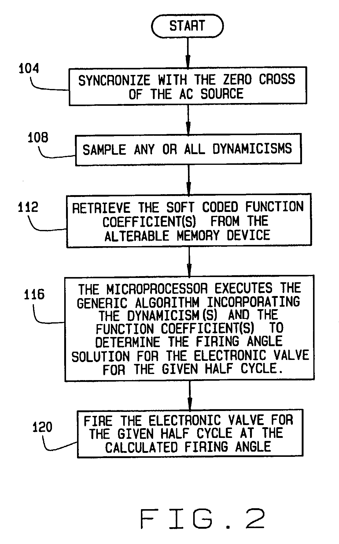
A method for controlling the operation of a motor utilizing a universal motor control module. The method includes sampling at least one motor operating criterion during operation of the motor and executing a universal control algorithm at a predetermined periodic interval of an AC line signal. Execution of the algorithm provides a firing angle solution for an electronic valve for each periodic interval, thereby controlling the behavior of the motor. Additionally, the method includes firing the electronic valve at the calculated firing angle during each periodic interval such that the motor functions in accordance with desired operational parameters.

Description

FIELD OF INVENTION[0001]The invention relates generally to systems and methods for controlling the operation of a motor. More specifically, the invention relates to a universal motor control module suitable for use with any of a variety of motors in any of a variety of motor applications.BACKGROUND OF THE INVENTION[0002]Typically, motors are controlled by dedicated analog or digital circuitry configured to control a specific motor in a specific application. For example, one dedicated circuit would be required to control a specific motor utilized in a power saw application, while another dedicated circuit would be required to control a different motor utilized in a drill application. Or further yet, one dedicated circuit would be required to control the motor utilized in the power saw application, while a different circuit would be required to utilize the same motor in a table saw application. Normally, each dedicated analog or digital control circuit would be constructed of differen...

Claims


Application Information

Patent Timeline
Patent Type & Authority Patents(United States)
IPC IPC(8): H02P1/54H02P3/00H02P5/00H02P5/46H02P29/00H02P25/14
CPCH02P25/14Y10S388/937
Inventor BROTTO, DANIELE C.
Owner BLACK & DECKER INC
Learn More