Power semiconductor module with detector for detecting main circuit current through power semiconductor element
a technology of semiconductor elements and detectors, applied in thermoelectric instruments, dc-ac conversion without reversal, instruments, etc., can solve the problems of increased module cost, high cost and power loss associated with shunt resistance, etc., and achieve the effect of reducing the size of the wiring area, and reducing the cost of the modul
- Summary
- Abstract
- Description
- Claims
- Application Information
AI Technical Summary
Benefits of technology
Problems solved by technology
Method used
Image
Examples
first embodiment
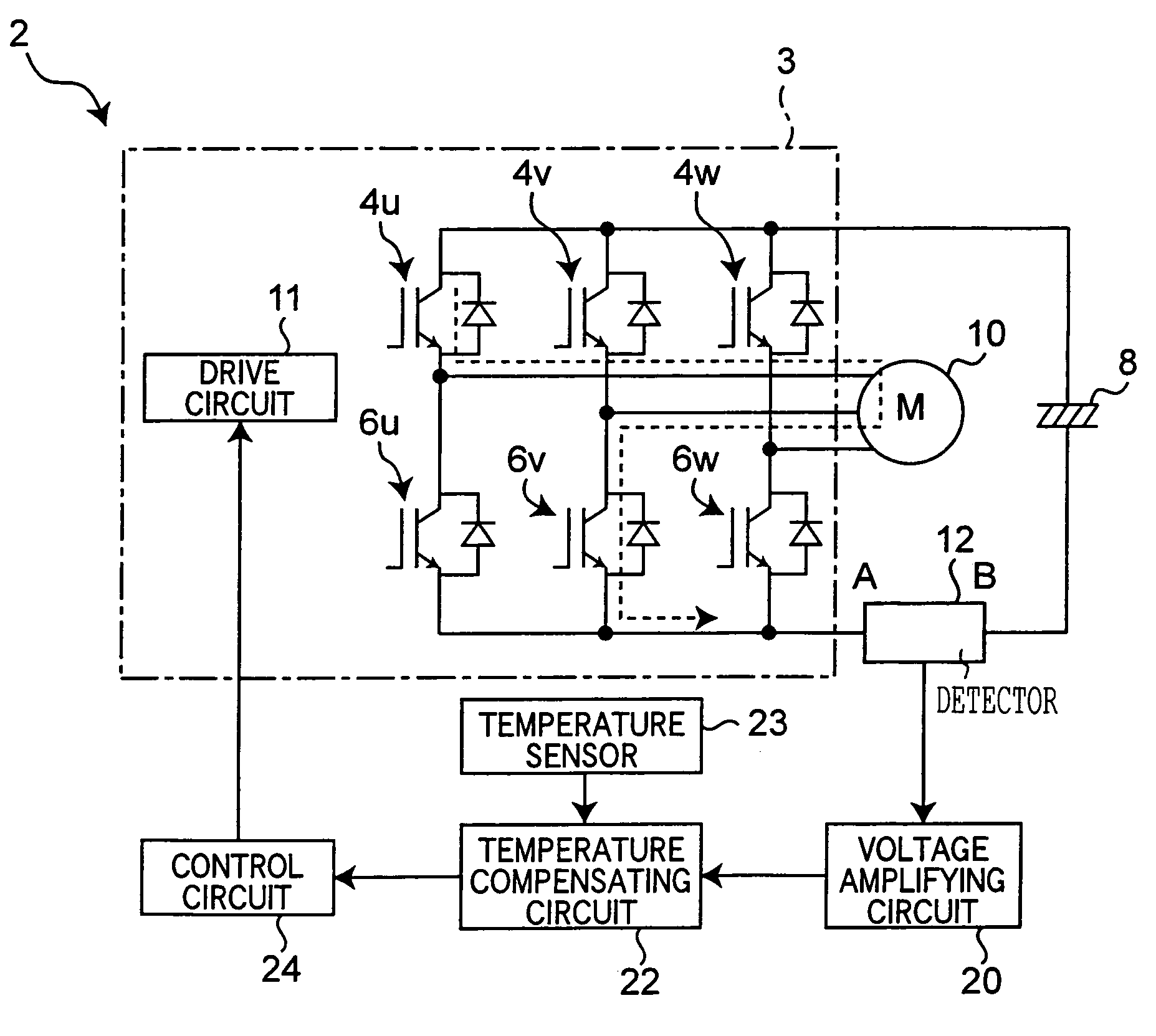
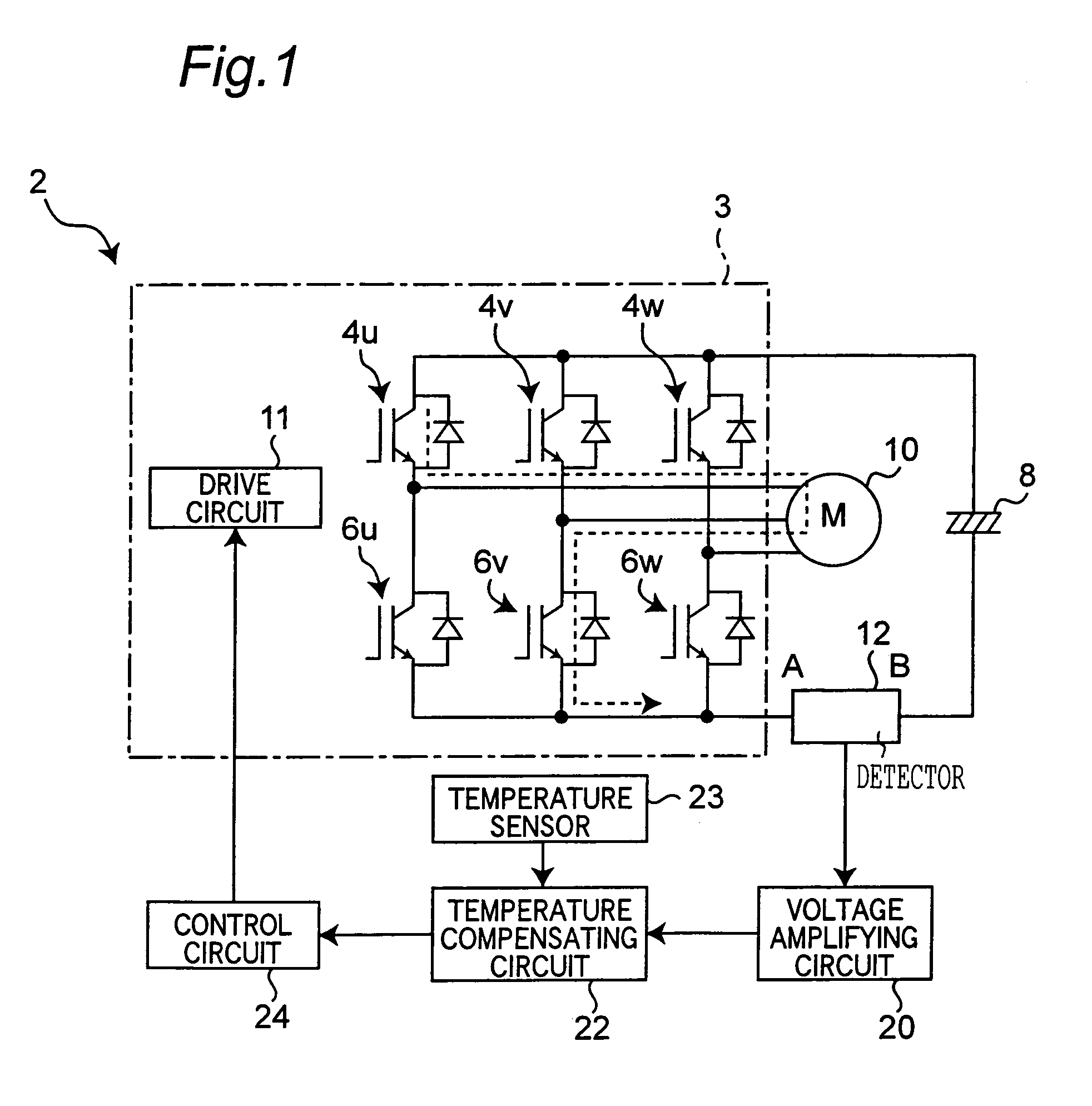
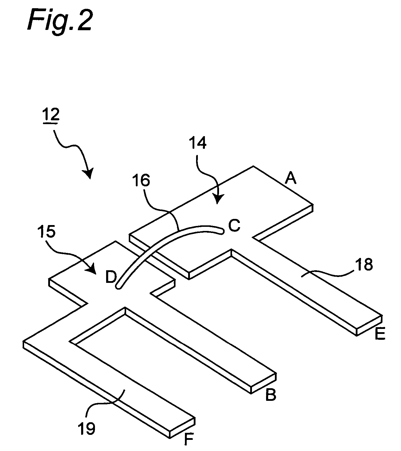
[0026]Referring to FIG. 1, there is shown a power semiconductor module, which is a first embodiment according to the present invention. The module 2 includes switching elements or IGBTs 4u, 4v, 4w, 6u, 6v and 6w connected in parallel and series with each other, which constitute an inverter circuit 3. Specifically, the switching elements 4u, 4v and 4w are U-phase, V-phase and W-phase elements of the upper arm, respectively, and their collector terminals are connected with the cathode of a DC power supply or electrolytic capacitor 8. The switching elements 6u, 6v and 6w are U-phase, V-phase and W-phase elements of the lower arm, respectively, and their emitter terminals are connected with the anode of the DC power supply 8. The emitter terminal of the U-phase switching element 4u of the upper arm is connected with the collector terminal of the U-phase switching element 6u of the lower arm and with an external load or motor 10. The emitter terminal of the V-phase switching element 4v o...
second embodiment
[0039]Referring to FIG. 3, a second embodiment of the present invention will be described hereinafter. In a description below, components identical or similar to those in the first embodiment are indicated by identical reference numbers or those with suffixes. The power semiconductor module 2a of the embodiment has a function to protect the switching elements where overcurrent is flown due to, for example, an excessive load to the motor 10 or short circuit. (i.e. current passes through the pair of switching elements connected in: parallel with each other). Specifically, the drive circuit 11a of the inverter circuit 3a for actuating the switching elements 4u, 4v, 4w, 6u, 6v and 6w is connected with a pair of voltage detection terminals not shown, which is connected with the terminal patterns 18 and 19 (FIG. 2) of the detector 12, so that the drive circuit receives a signal indicative of a potential difference across the bonding wire 16 (FIG. 2). For instance, if current flows from th...
third embodiment
[0042]Referring to FIG. 4, a third embodiment of the present invention will now be described. Each of the power semiconductor modules of the present embodiment and embodiments described later is similar to the module 2 shown in FIG. 1 except that circuit patterns of the detector for detecting a potential difference across the bonding wire are different from those in the first embodiment.
[0043]In the embodiment, like the detector 12 of the power semiconductor module 2, the detector 12b includes a pair of circuit patterns 14b and 15b connected via the bonding wire 16. A pair of terminal patterns 18b and 19b is extended from near bonding points C and D of the pair of the circuit patterns 14b and 15b, respectively. The pair of terminal patterns 18b and 19b is connected at output ports E and F with a pair of voltage detection terminals not shown with high impedance. In the embodiment, the circuit pattern 15b is formed so that a portion thereof (region G) is adjacent to and generally para...
PUM
 Abstract
Description
Claims
Application Information
 - R&D
- Intellectual Property
- Life Sciences
- Materials
- Tech Scout
- Unparalleled Data Quality
- Higher Quality Content
- 60% Fewer Hallucinations
Browse by: Latest US Patents, China's latest patents, Technical Efficacy Thesaurus, Application Domain, Technology Topic, Popular Technical Reports.
© 2025 PatSnap. All rights reserved.Legal|Privacy policy|Modern Slavery Act Transparency Statement|Sitemap|About US| Contact US: help@patsnap.com


