Automatic installation and alignment mode for wireless bridges

a wireless bridge and automatic installation technology, applied in the field of installing or aligning bridges, can solve the problems of current installation procedures and safety hazards of installation procedures, and achieve the effect of facilitating communication and facilitating communication

Inactive Publication Date: 2006-09-05
CISCO TECH INC
View PDF9 Cites 78 Cited by
  • Summary
  • Abstract
  • Description
  • Claims
  • Application Information

AI Technical Summary

Benefits of technology

[0012]In a further embodiment, an antenna of the first bridge is adjusted until the indicated signal strength reaches a maximum value. In one aspect, the antenna is adjusted without using a measuring device to measure an output signal that is output from the first bridge or interfacing a processing device with the first bridge. In a specific implementation, a plurality of received signal strength values of signals sent by the second bridge to the first bridge are obtained and stored The indicated signal strength is an average of the plurality of received signal strengths. In one aspect, the indicated signal strength is displayed until an installation mode of the first bridge completes. In another aspect, the indicated signal strength is displayed until optimum indicated signal strength is reached.
[0013]In another embodiment, the invention pertains to a computer system operable to install or align a bridge for facilitating communication between nodes in a wireless computer network. The computer system includes one or more processors and one or more memory. At least one of the memory and processors are adapted to provide at least some of the above described method operations. In yet a further embodiment, the invention pertains to a computer program product for installing or aligning a bridge for facilitating communication between nodes in a wireless computer network. The computer program product has at least one computer readable medium and computer program instructions stored within at least one of the computer readable product configured to perform at least some of the above described method operations.
[0014]These and other features and advantages of the present invention will be presented in more detail in the following specification of the invention and the accompanying figures which illustrate by way of example the principles of the invention.

Problems solved by technology

Unfortunately, current installation procedures present several disadvantages.
Since wireless bridges are typically installed on building roofs, the installation procedure also presents a safety hazard when performing these various physical installation tasks together or it requires more than one person to complete the installation.

Method used


Image

  • Automatic installation and alignment mode for wireless bridges
  • Automatic installation and alignment mode for wireless bridges
  • Automatic installation and alignment mode for wireless bridges

Examples


Embodiment Construction

[0022]Reference will now be made in detail to a specific embodiment of the invention. An example of this embodiment is illustrated in the accompanying drawings. While the invention will be described in conjunction with this specific embodiment, it will be understood that it is not intended to limit the invention to one embodiment. On the contrary, it is intended to cover alternatives, modifications, and equivalents as may be included within the spirit and scope of the invention as defined by the appended claims. In the following description, numerous specific details are set forth in order to provide a thorough understanding of the present invention. The present invention may be practiced without some or all of these specific details. In other instances, well known process operations have not been described in detail in order not to unnecessarily obscure the present invention.

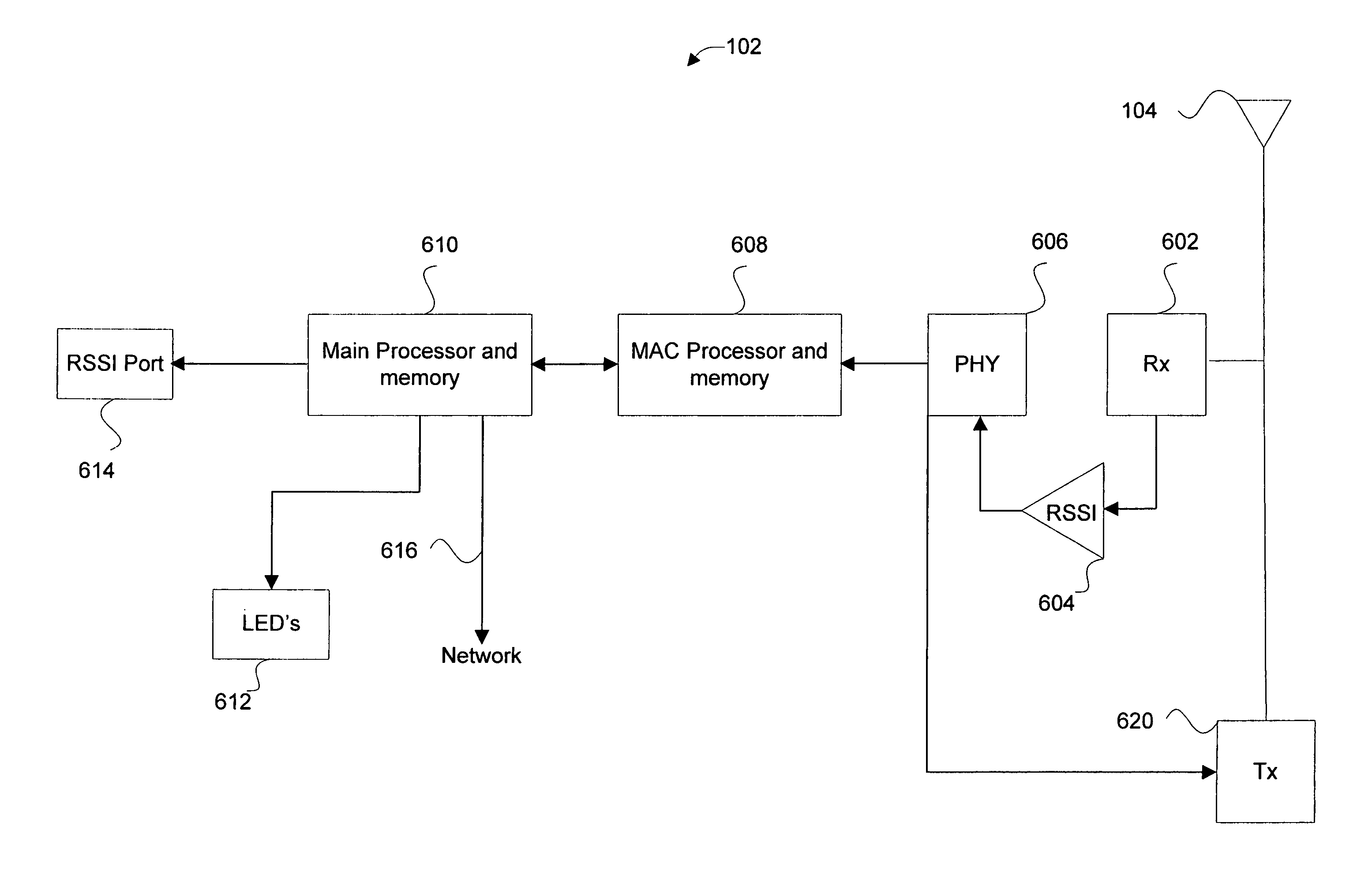
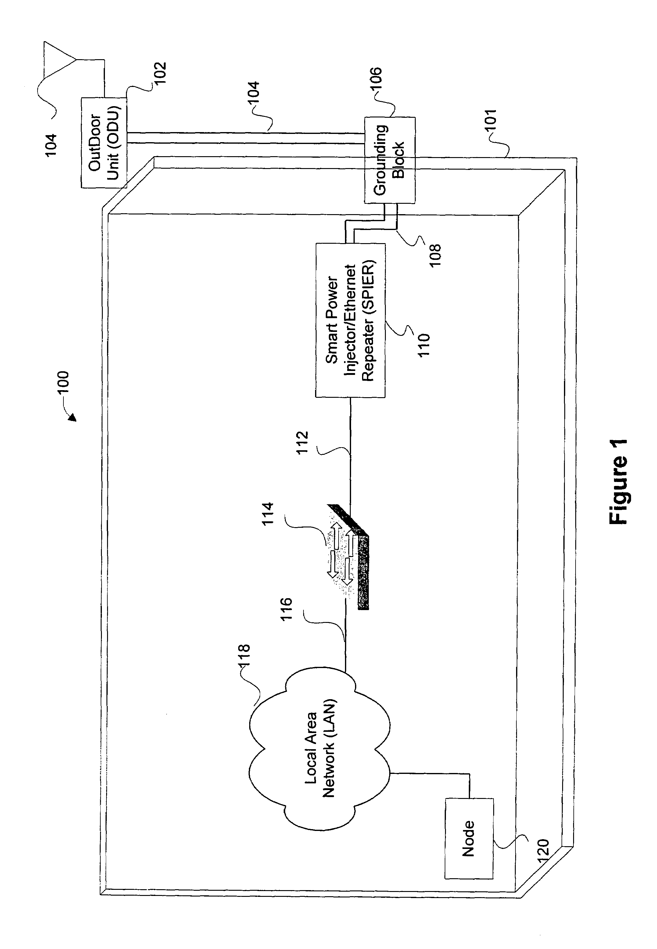
[0023]FIG. 1 is a diagrammatic representation of a bridge which is installed at a first location 100 in acco...


PUM


Abstract

Disclosed are methods and apparatus for automatically installing and/or aligning antennas of wireless bridges in computer networks. In general terms, when a particular bridge is installed or aligned, an installation mode is triggered which automatically displays an indication of one or more signal strength levels of signals received into the particular bridge. In the automatic installation mode, the particular bridge automatically searches for a remote bridge with which it can associate. After a remote bridge is associated with the particular bridge, the signal strength received by the particular bridge from the found bridge is then displayed on one or more indicators, such as light emitting diodes. Thus, one can then adjust the antenna of the bridge until an optimum power level is achieved without using any specialized equipment, such as a voltmeter or laptop for interfacing with the bridge to obtain the signal strength indication.

Description

BACKGROUND OF THE INVENTION[0001]The present invention relates to methods and apparatus for facilitating use of wireless computer networks. More specifically, it relates to installing or aligning bridges in wireless networks.[0002]A wireless network typically includes two or more processing nodes which communicate through their own respective bridge devices. That is, a first node is coupled to a first bridge and a second node is coupled to a second bridge. Each bridge is also configured to receive signals from the other bridge via an internal or external antenna. For example, a first node sends a signal through its own bridge, which then wirelessly transmits the signal to a second node's bridge. Each bridge generally process signals received and transmitted by their respective nodes.[0003]When a wireless network is set up between two or more nodes located at two different sites, a bridge is installed at each site. At least part of the bridge is usually installed on the outside or ro...

Claims


Application Information

Patent Timeline
Patent Type & Authority Patents(United States)
IPC IPC(8): G08B21/00G06F15/16H04Q7/20H04W24/00H04W40/24H04W88/08H04W88/14
CPCH04L12/4625H04W88/14H04W88/085H04W24/00H04W40/246Y02D30/70
Inventor TASKIN, METIN ISMAILBILSTAD, ARNOLD MARKGAUGER, GLADE L.
Owner CISCO TECH INC
Why Eureka
Try Eureka