Tamper-indicating radio frequency identification antenna and sticker, a radio frequency identification antenna, and methods of using the same

a radio frequency identification and sticker technology, applied in the direction of collapsible antenna means, burglar alarm mechanical actuation, instruments, etc., can solve the problem of rfid capability of rfid components being disabled

Inactive Publication Date: 2006-09-05
3M INNOVATIVE PROPERTIES CO
View PDF67 Cites 58 Cited by
  • Summary
  • Abstract
  • Description
  • Claims
  • Application Information

AI Technical Summary

Benefits of technology

[0005]One aspect of the present invention provides a tamper-indicating radio frequency identification device. The radio frequency identification device comprises: a substrate including a first major surface and a second major surface opposite the first major surface; and a radio frequency identification antenna attached to the first major surface of the substrate, where said ante

Problems solved by technology

Additionally, the tamper rack can be formed such that it is damaged when the label is tampered.
Alternatively, th

Method used


Image

  • Tamper-indicating radio frequency identification antenna and sticker, a radio frequency identification antenna, and methods of using the same
  • Tamper-indicating radio frequency identification antenna and sticker, a radio frequency identification antenna, and methods of using the same
  • Tamper-indicating radio frequency identification antenna and sticker, a radio frequency identification antenna, and methods of using the same

Examples


Embodiment Construction

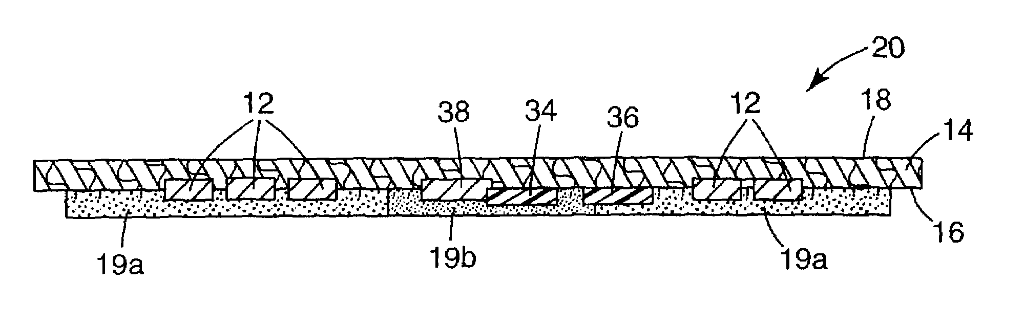
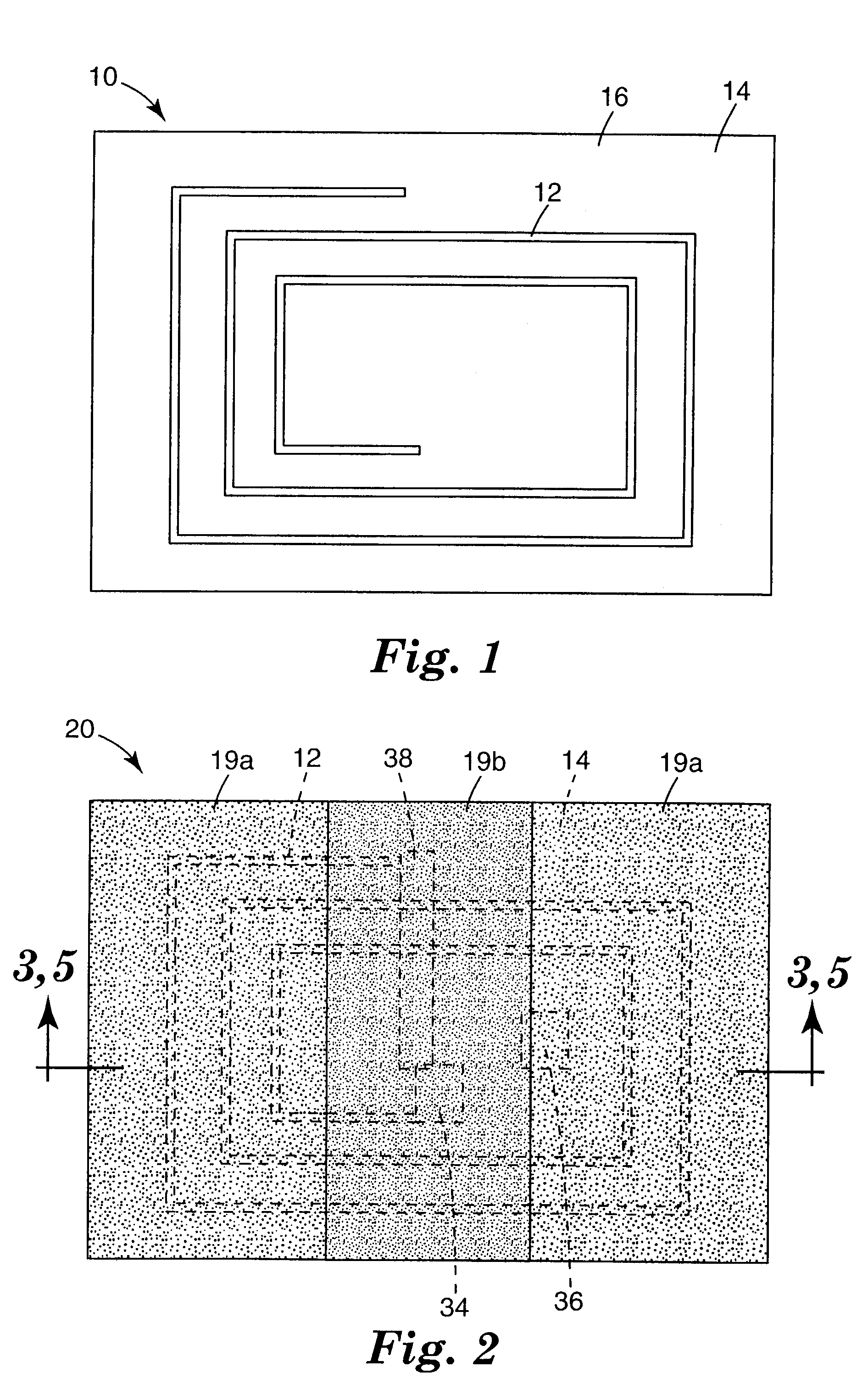
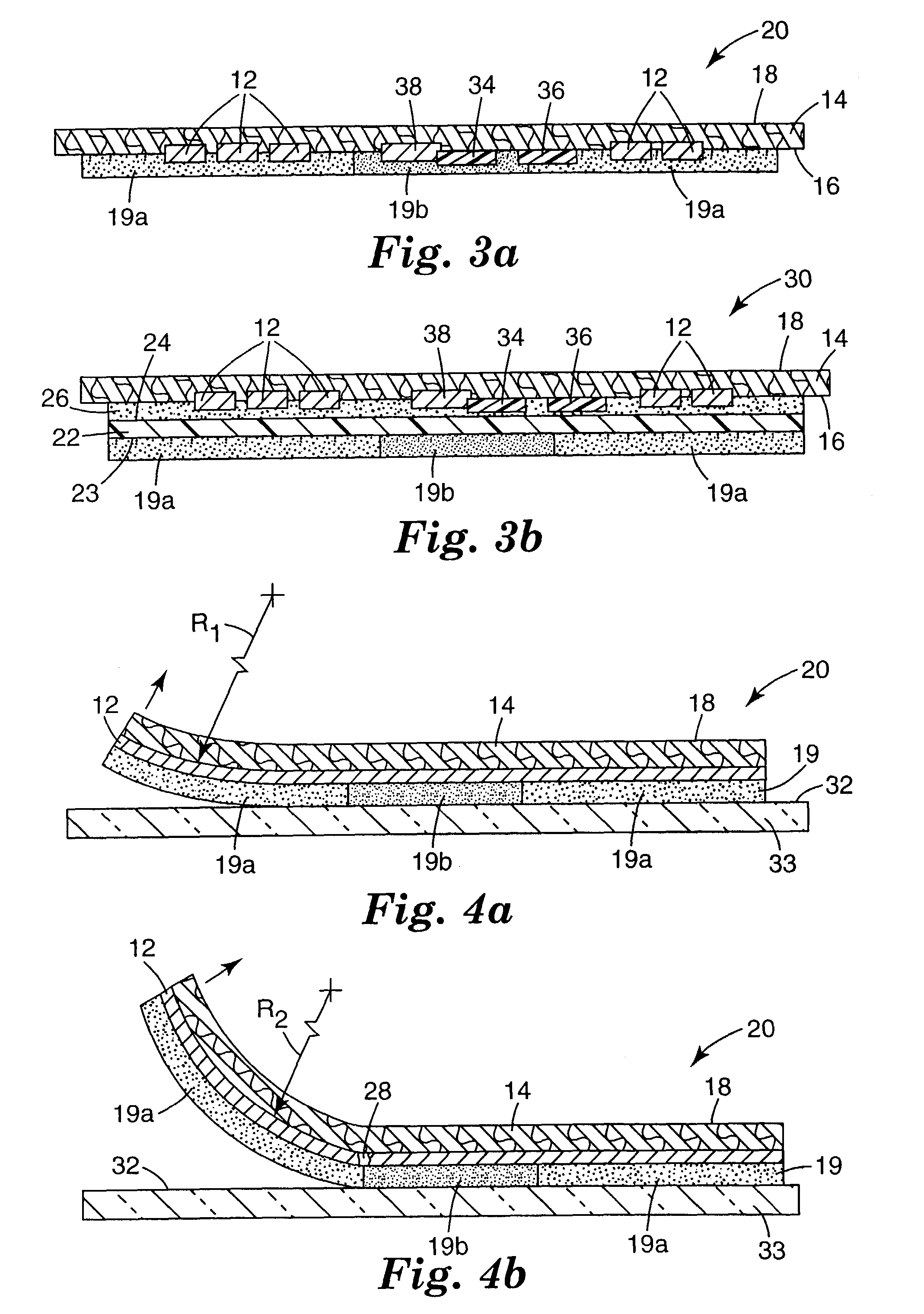
[0027]FIG. 1 illustrates one preferred embodiment of a radio frequency identification (“RFID”) device 10. The RFID device 10 includes a substrate 14, which has a first major surface 16 and a second major surface 18 opposite the first major surface (shown in FIG. 3a). The substrate 14 is preferably a compressible material. As used herein, compressible means that a substrate reduces in its dimension parallel to an applied pressure and that the total volume of the substrate is also reduced by a similar amount. When used herein as a quantitative measure, X % compressible means that the dimension of a substrate measured parallel to an applied pressure of 30 MPa is [(100−X) / 100] times its dimension in this direction at 0.07 MPa and the total volume of the substrate at 30 MPa is [(100−X) / 100] times its volume at 0.07 MPa. If the dimension change in the direction of the applied pressure and the volume change yield different values of X, then the smaller X of the two values is used to define...


PUM

PropertyMeasurementUnit
Lengthaaaaaaaaaa
Lengthaaaaaaaaaa
Fractionaaaaaaaaaa

Abstract

A tamper-indicating radio frequency identification device made of densified metal powder and to a sticker including the same device. The present invention also relates to radio frequency identification antenna made of densified metal powder and to a sticker including the same antenna. The present invention also relates to methods of indicating that a radio frequency identification antenna or sticker has been tampered with.

Description

TECHNICAL FIELD[0001]The present invention relates to a tamper-indicating radio frequency identification device made of densified metal powder and to a sticker including the same antenna. The present invention also relates to radio frequency identification antenna made of densified metal powder and to a sticker including the same antenna. The present invention also relates to methods of indicating that a radio frequency identification antenna or sticker has been tampered with.BACKGROUND OF THE INVENTION[0002]Radio frequency identification technology has become widely used in virtually every industry, including transportation, manufacturing, waste management, postal tracking, airline baggage reconciliation, and highway toll management. An RFID system is made up of two components, the transponder and the interrogator or reader. The essential components of a transponder are the data carrying device—generally referred to as an integrated circuit or an electronic microchip, and a couplin...

Claims


Application Information

Patent Timeline
IPC IPC(8): G08B13/14G06K19/073G06K19/077H05K3/10
CPCG06K19/027G06K19/073G06K19/0739G06K19/07749B22F2998/00H05K3/102C22C1/04G06K19/077
Inventor KUHNS, DAVID W.
Owner 3M INNOVATIVE PROPERTIES CO
Why Eureka
Try Eureka