AI technical title is built by Patsnap AI team. It summarizes the technical point description of the patent document.
a reflector and waveguide technology, applied in waveguides, antennas, electrical equipment, etc., can solve the problems of affecting the operation of the reflector
Active Publication Date: 2006-09-05
ROCKWELL COLLINS INC
View PDF4 Cites 236 Cited by
Summary
Abstract
Description
Claims
Application Information
AI Technical Summary
This helps you quickly interpret patents by identifying the three key elements:
Problems solved by technology
Method used
Benefits of technology
Benefits of technology
[0011]It is an advantage of the present invention to provide multiple bands at a common phase center.
[0012]It is an advantage of the present invention to provide the ability to mix and match modes across concentric ring sections.
[0014]It is a feature of the present invention to provide simultaneous right-hand circular polarization and left-hand circular polarization for each band possible.
[0015]It is a feature of the present invention to provide dual-band operation with perfect electrical conductor and on-band electromagnetic band gap structures in a waveguide feed section.
Problems solved by technology
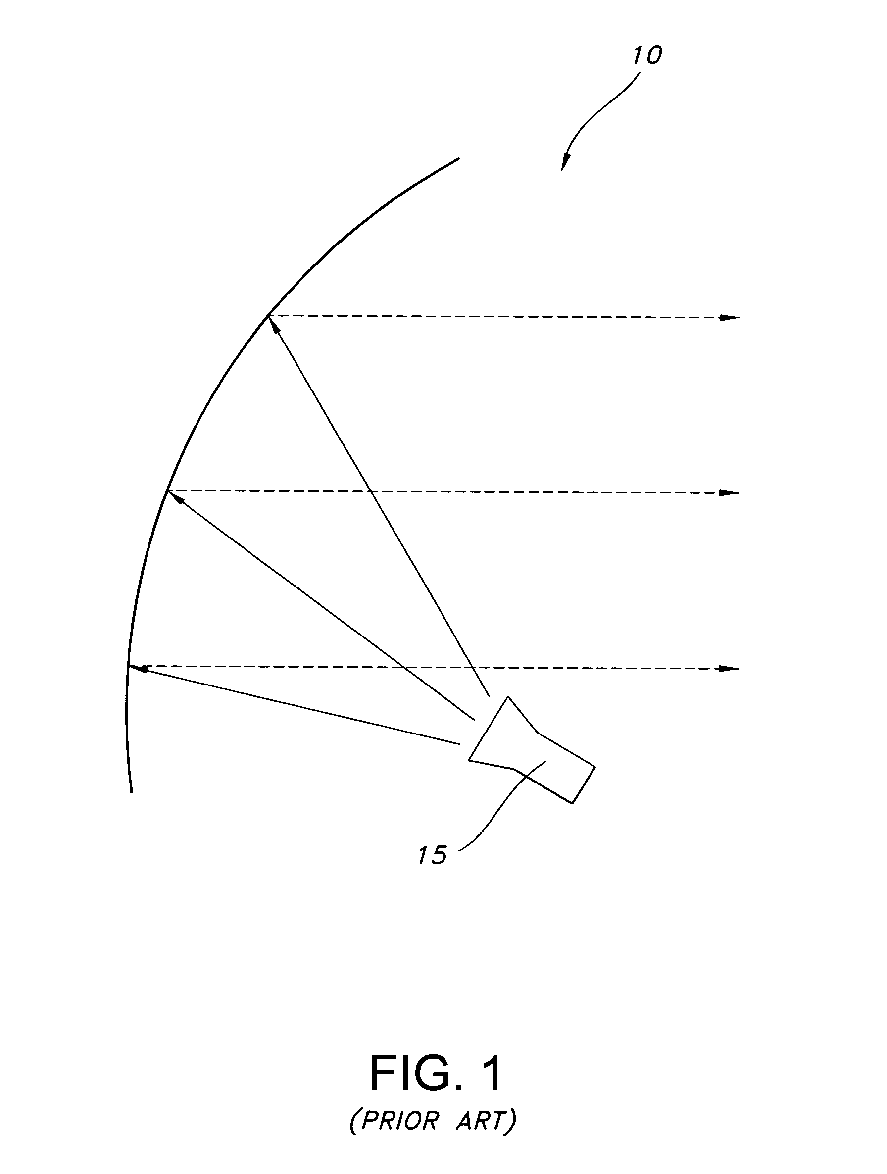
With the traditional waveguide feed 15 the realization of more than two bands is difficult.
Multiband feeds can be mechanically large and therefore initiate excessive aperture blockage for many reflector applications.
The feed assemblies are mechanically complex and difficult to manufacture, which adds to weight and cost.
They are mechanically complex and are not suitable for moderate and small-sized reflectors due to large aperture blockage.
Method used
Image
Click on the blue label to locate the original text in one second.
Reading with bidirectional positioning of images and text.
Examples
first embodiment
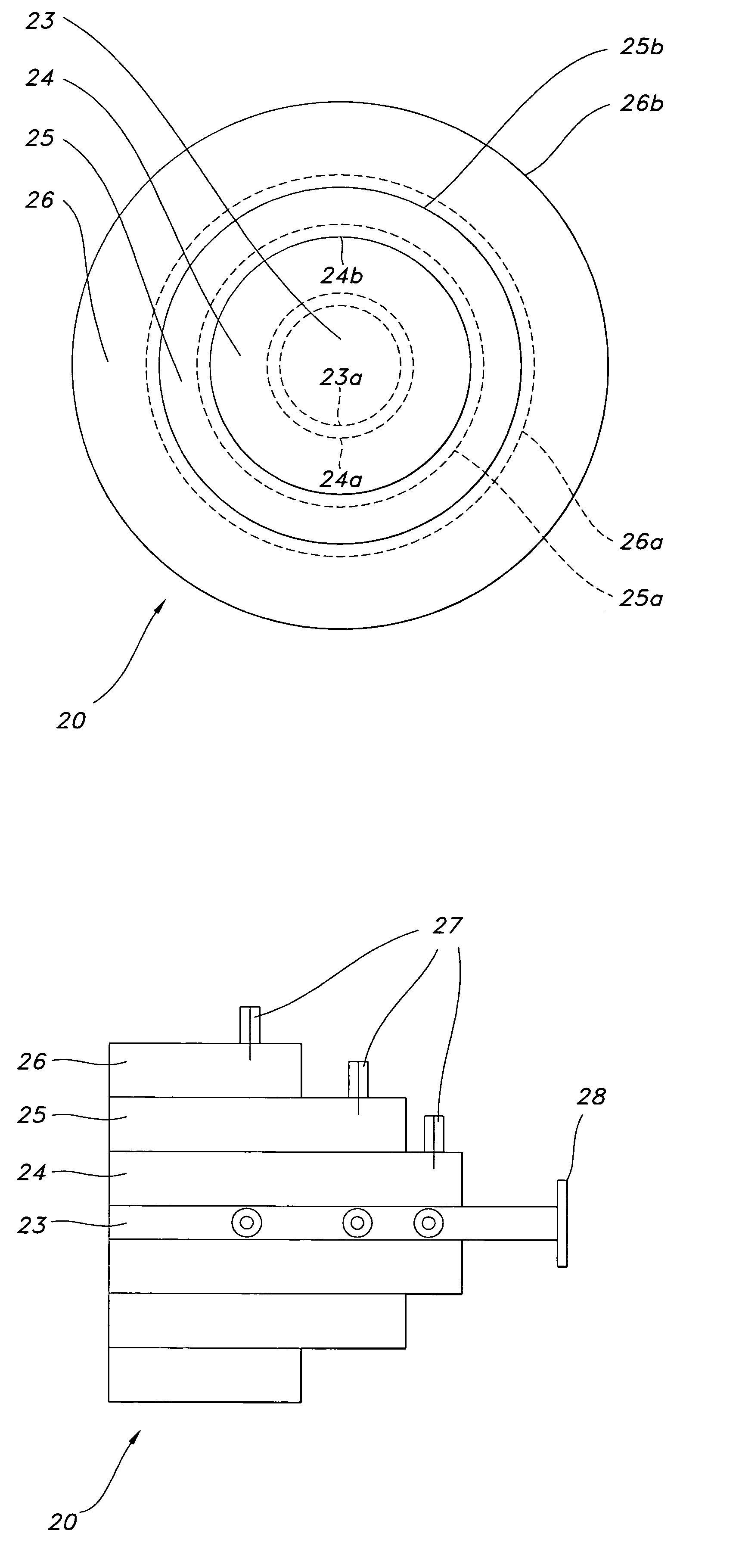
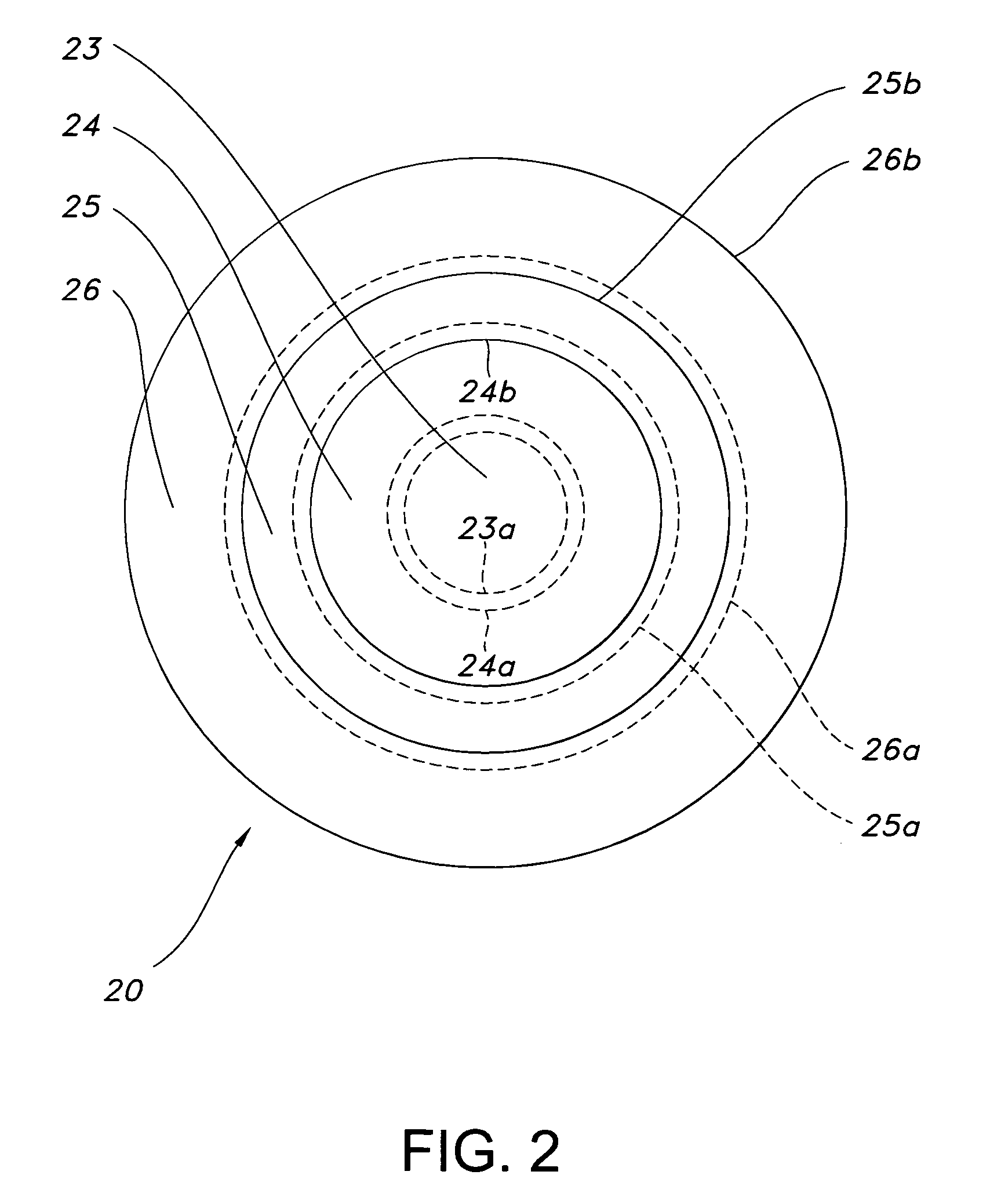
[0029]the present invention is an all-metallic coaxial waveguide structure 20 consisting of a highest frequency TE11 waveguide structure, which is the band 1 waveguide 23 of FIGS. 2 and 3 surrounded by concentric rings of TE11 coaxial waveguide sections for the remaining lower band frequencies, band 2 waveguide 24, band 3 waveguide 25, and band 4 waveguide 26. In the all-metallic coaxial waveguide 20, the EBG structures shown as dashed concentric rings 23a, 24a, 25a, and 26a in FIG. 2 are to be considered as solid rings for the purposes of the all-metallic feed embodiment discussion.
[0030]At the highest frequency, the band 1 center waveguide section 23 operates in the standard TE11 mode shown in FIG. 4. The cutoff frequency for the TE11 mode is commonly known in the art as:
[0035]The radius of the band 1 waveguide center section 23 is typically selected with regard to minimum ins...
second embodiment
[0046]the present invention utilizes EBG or PMC surfaces, also known as hard surfaces, for waveguide surfaces conductors as shown by the dashed rings 23a, 24a, 25a, and 26a in FIG. 2 in exemplary fashion. The waveguide inner conductors 24a, 25a, and 26a and the waveguide outer conductors 23a, 24b, 25b, and 26b may be metallic PEC or PMC (EBG) as described below for possible waveguide mode options for the waveguides 23, 24, 25, and 26 of FIG. 2.[0047]I. A TEM mode for a circular waveguide section 23 with EBG surface outer conductor 23a as shown in FIG. 6.[0048]II. A TEM mode for coaxial waveguide sections 24, 25, and 26 if the outer conductors (24b, 25b, and 26b) and inner conductors (24a, 25a, and 26a) are EBG surfaces. The field structure is similar to FIG. 6.[0049]III. A circular waveguide-like TE11, mode for coaxial waveguide sections 24, 25, and 26 whose outer conductors (24b, 25b, and 26b) are PEC and whose inner conductors (24a, 25a, and 26a) are PMC (EBG). This field structur...
PUM
Abstract
A multiband waveguide reflector antenna feed comprises waveguide feeds in a concentric architecture. A waveguide feed is located in the center and coaxial waveguide feeds are disposed around the center feed. The waveguide feeds may be all-metallic with the center feed operating in a TE11 mode and the coaxial feeds operating in a coaxial TE11 mode. The waveguide feeds may have electromagnetic band gap (EBG) surfaces on waveguide surfaces. The center waveguide feed may have an EBG outer conductor surface and operate in a circular waveguide TEM mode. The coaxial waveguide feeds may have EBG inner and outer conductors and operate in a circular waveguide TEM mode. The coaxial feeds may have EBG inner conductors and near perfect electrical conductor (PEC) outer conductors and operate in a circular waveguide-like TE11 mode or may comprise EBG outer conductors and PEC inner conductors and operate in a quasi-TEM waveguide mode.
Description
BACKGROUND OF THE INVENTION[0001]This invention relates to antennas, reflector antennas, and specifically to a multiband waveguide reflector antenna feed.[0002]Contemporary military satellite communication (SATCOM) systems require cost-effective, light-weight, low-mass, multiband and polarization-agile antenna apertures. Specific SATCOM bands of current interest include C-band, X-band, Ku-band (10.7–12.7 GHz), K-band (20–22 and 29–31 GHz) and Q-band (43–45 GHz) for various military and commercial SATCOM systems. In addition, the ability to receive orthogonal polarized signals within the same band is a requirement for military SATCOM systems. An example of this is the requirement to simultaneously receive SCAMP MILSTAR (21-GHz right-hand circular polarization (RHCP)) and Global Broadcast System (GBS) video link (21-GHz left-hand circular polarization (LHCP)).[0003]A traditional metallic waveguide feed 15 for a reflector antenna 10 is illustrated in FIG. 1 and represents the current a...
Claims
Application Information
Patent Timeline
Application Date:The date an application was filed.
Publication Date:The date a patent or application was officially published.
First Publication Date:The earliest publication date of a patent with the same application number.
Issue Date:Publication date of the patent grant document.
PCT Entry Date:The Entry date of PCT National Phase.
Estimated Expiry Date:The statutory expiry date of a patent right according to the Patent Law, and it is the longest term of protection that the patent right can achieve without the termination of the patent right due to other reasons(Term extension factor has been taken into account ).
Invalid Date:Actual expiry date is based on effective date or publication date of legal transaction data of invalid patent.

