Eureka AIR delivers breakthrough ideas for toughest innovation challenges, trusted by R&D personnel around the world.

Spatial patches for graphics rendering

a technology of graphics and patches, applied in the field of computer graphics, can solve the problems of no real displacement of pixels, and poor approximation of polygonal mesh representations of real-world objects having shapes,

Inactive Publication Date: 2006-09-05
MOSCOW STATE UNIVERSITY +1
View PDF10 Cites 25 Cited by
  • Summary
  • Abstract
  • Description
  • Claims
  • Application Information

AI Technical Summary

Benefits of technology

The invention is about a method and apparatus for representing a graphical object with one or more spatial patches. The invention aims to overcome the limitations of traditional methods that use polygonal mesh representations, which poorly represent smoothly varying surfaces. The invention uses a triangular mesh representation with texture maps to provide a more accurate representation of real-world objects. The invention also introduces a new method for approximating illumination from the surface of a three-dimensional object using bump mapping. Overall, the invention improves the accuracy and realism of computer graphics by using a spatial patch representation of objects.

Problems solved by technology

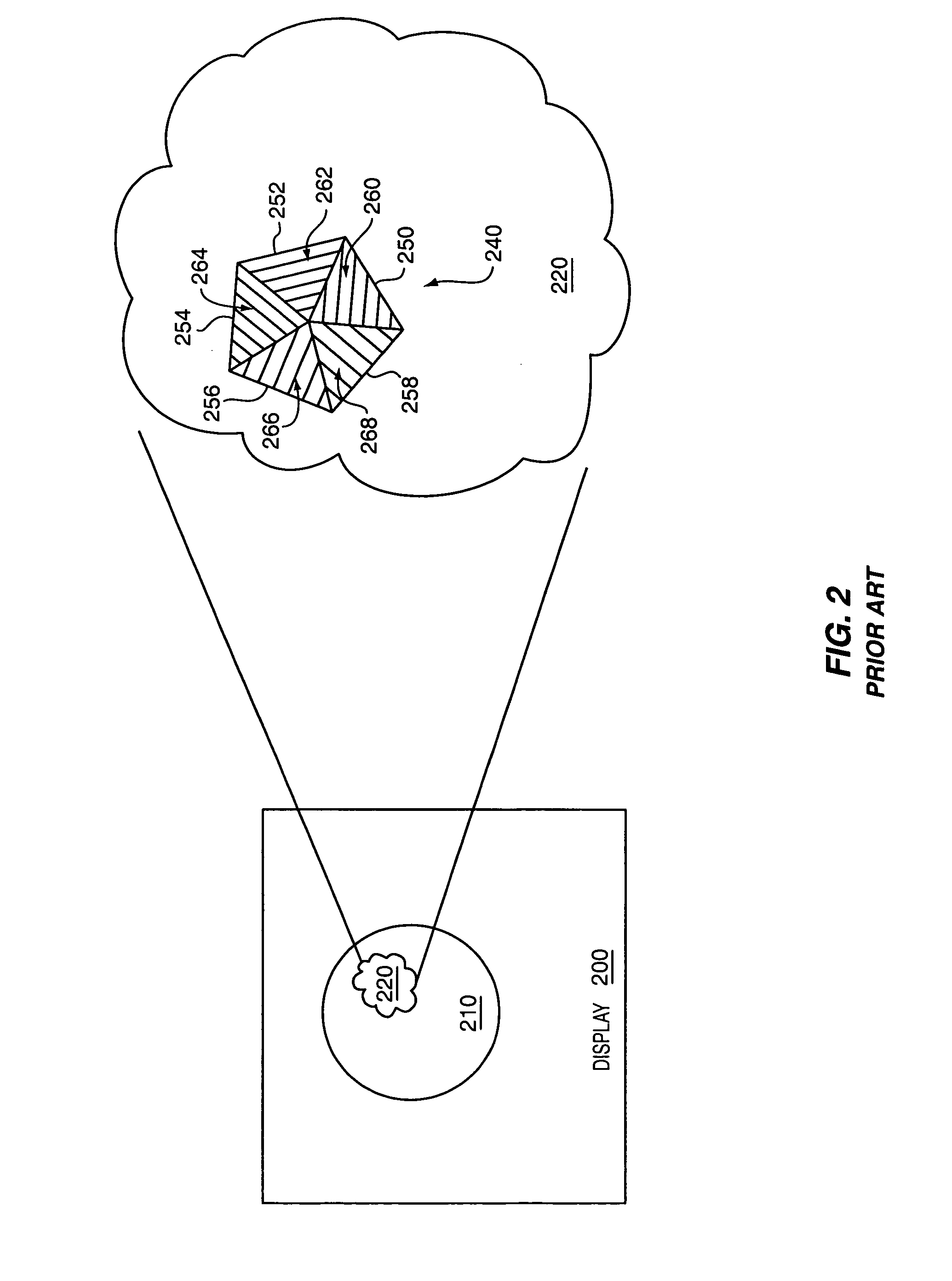
This example represents a general and major problem with polygonal mesh representations, namely that polygonal mesh representations provide poor approximations of real-world objects having shapes that vary smoothly, rather than in discrete planes corresponding to the polygonal boundaries. FIG. 3 shows an exemplary human head 300 represented using a prior art triangular mesh representation.
However, no real displacement of pixels is achieved, and bump mapping techniques are not effective for silhouettes and other surfaces that do not directly face the virtual camera.
Among other problems with bump mapping, the bump maps require additional storage and self occlusion does not happen correctly.
Accordingly, in the prior art, the only practical way of overcoming the limitation illustrated in FIG. 3 is to provide a large number of very small polygons, which significantly increases the number of computations and slows rendering.
Often such sacrifices are not acceptable.
Accordingly, in the prior art approaches the need to rapidly display computer graphics has forced an inaccurate and unnatural approach for representing real-world objects, and such approaches are limiting the visual quality and appeal of the computer graphics.

Method used


Image

  • Spatial patches for graphics rendering
  • Spatial patches for graphics rendering
  • Spatial patches for graphics rendering

Examples


Embodiment Construction

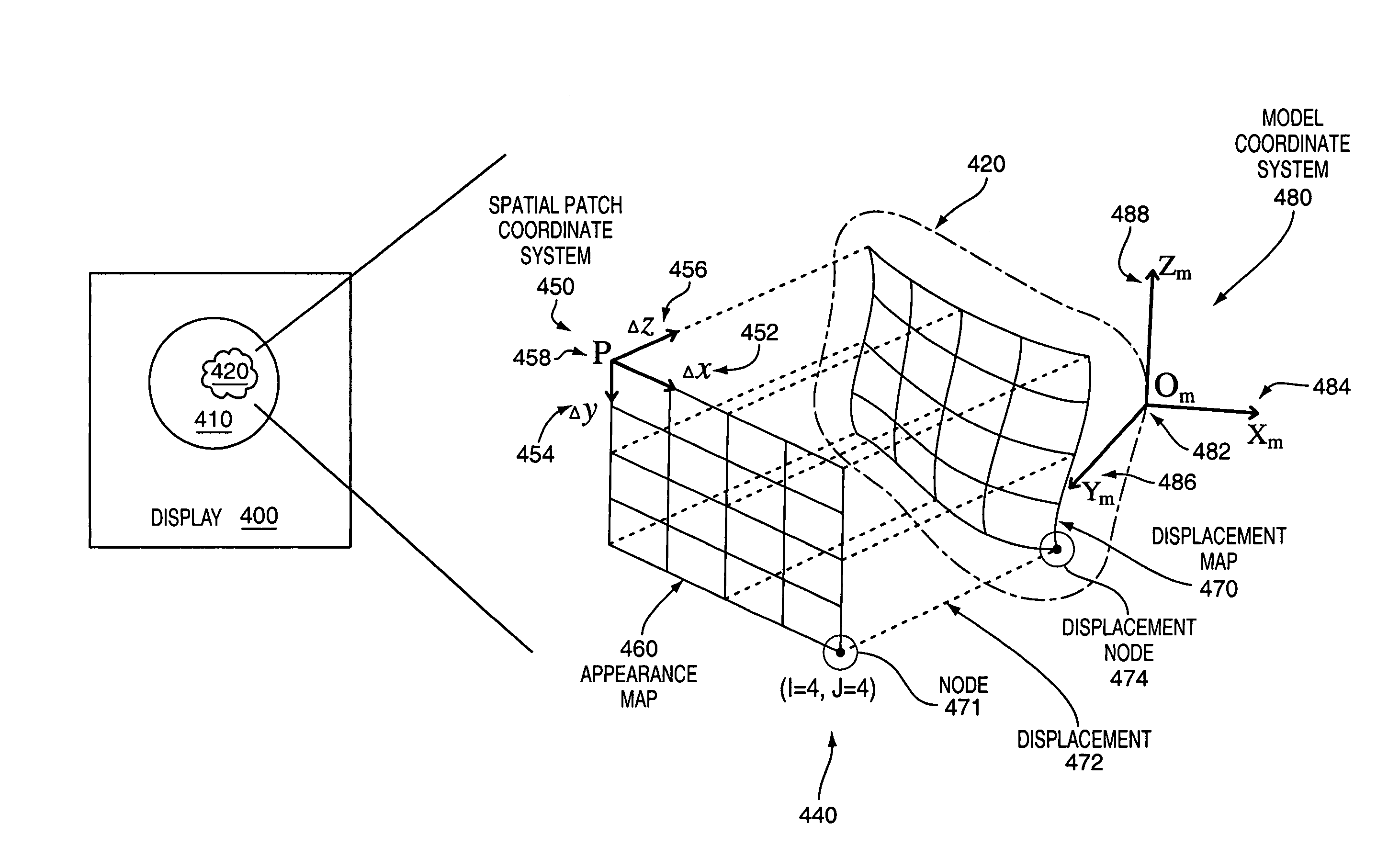
[0031]A method and apparatus are described for representing an object with one or more spatial patches and processing the one or more spatial patches to create computer graphics for the object. The spatial patch may include displacement data to represent the geometry of the object and appearance data to represent the color of the object. Advantageously, such representations may provide a more accurate representation of the object with less data and may allow the creation of more appealing computer graphics.

[0032]In the following description, for the purpose of explanation, numerous specific details are set forth in order to provide a thorough understanding of the present invention. It will be apparent, however, to one skilled in the art that the present invention may be practiced without some of these specific details. In other instances, well-known structures and devices are shown in block diagram form.

Exemplary Spatial Patch

[0033]FIG. 4 conceptually shows representing a surface po...


PUM


Abstract

Described are a novel graphical element known as a spatial patch and a system and method for rendering the spatial patch to create computer graphics. The spatial patch may include appearance data and displacement data for each of a plurality of nodes that together specify the color and geometry for typically a small portion of a surface of an object. The appearance and displacement data may be independent and irregular for each of the nodes in order to represent complexly colored and structured objects. The spatial patch may be processed independently and may have internal topology or structure to facilitate parallel processing. Accordingly, the spatial patch offers many quality and processing advantages over polygon mesh representations that have previously been used to create three-dimensional computer graphics.

Description

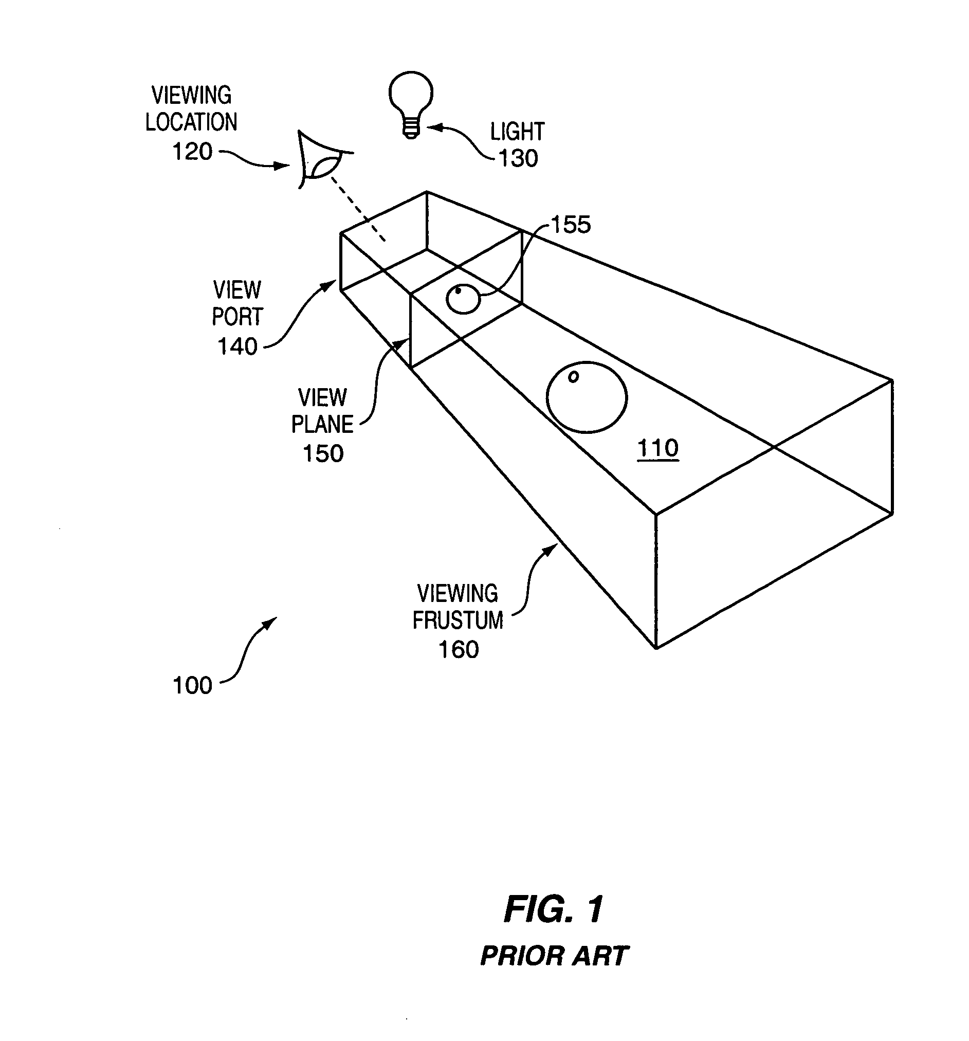
COPYRIGHT NOTICE[0001]Contained herein is material that is subject to copyright protection. The copyright owner has no objection to the facsimile reproduction of the patent disclosure by any person as it appears in the Patent and Trademark Office patent files or records, but otherwise reserves all rights to the copyright whatsoever.BACKGROUND OF THE INVENTION[0002]1. Field of the Invention[0003]The invention relates generally to the field of computer graphics. More particularly, the invention relates to a method and apparatus for representing a graphical object with one or more spatial patches and rendering the graphical object based on this representation.[0004]2. Background Information[0005]In order to provide accurate and immersing computer graphics, it is desirable to use computer graphics models that accurately represent the visual qualities of real-world objects. FIG. 1 illustrates a three-dimensional stage 100 that is at least conceptually used by many computer graphical mode...

Claims


Application Information

Patent Timeline
Patent Type & Authority Patents(United States)
IPC IPC(8): G06T17/00G06T17/20
CPCG06T17/20
Inventor RESHETOV, ALEXANDER V.KUZMIN, YEVGENIY P.IVANOV, DENIS V.YAKOVLEV, ALEXANDER N.
Owner MOSCOW STATE UNIVERSITY
Why Eureka
Eureka Blog
Learn More