Radiation scanning of objects for contraband

a technology of object radiation and contraband, applied in the direction of material analysis, application, material analysis using wave/particle radiation, etc., can solve the problems of difficult to distinguish between, difficulty in identifying dangerous items, and difficulty in identifying thin sheets of explosive materials

Inactive Publication Date: 2006-09-05
VAREX IMAGING CORP
View PDF78 Cites 216 Cited by
  • Summary
  • Abstract
  • Description
  • Claims
  • Application Information

AI Technical Summary

Benefits of technology

[0023]At least one of the sources may emit radiation having a first energy distribution and at least one of the sources may emit radiation having a second energy distribution different than the first energy distribution. Alternatively,...

Problems solved by technology

One disadvantage of radiographic imaging is that all items within the object in the path of the radiation beam are superimposed on the image.
If there are many items in the object, it may be difficult to distinguish among them.
The identification of dangerous items is thereby hampered.
Thin sheets of explosive materials may also be difficult to identify on a radiograph, particularly if they are oriented perpendicular to the scanning beam.
However, reconstruction of CT images of an object requires a large number of scans of the object at a plurality of angles.
Conducting a sufficient number of scans for CT reconstruction is time consuming.
Depending on the system used, CT imaging of an entire piece of luggage may be too slow for practical use in screening luggage in airports, for example.
While the smuggling of contraband such as guns and explosives onto planes in carry-on bags and in luggage has been a well known, ongoing concern, a less publicized but also serious threat is the smuggling of contraband across borders and by boat in large cargo containers.
Since only bags that fit through the tunnel may be inspected, such systems cannot be used to ins...

Method used


Image

  • Radiation scanning of objects for contraband
  • Radiation scanning of objects for contraband
  • Radiation scanning of objects for contraband

Examples


Embodiment Construction

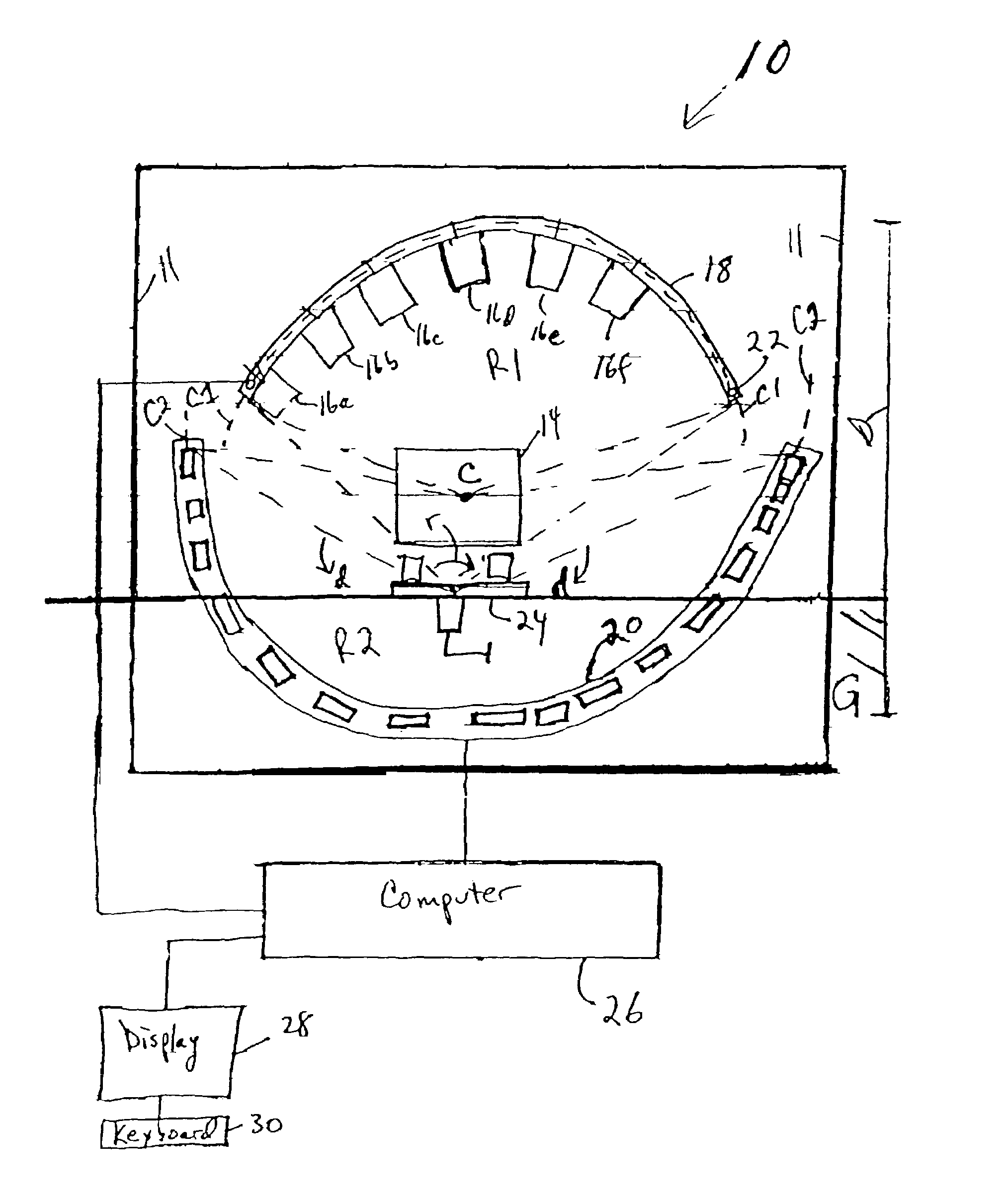
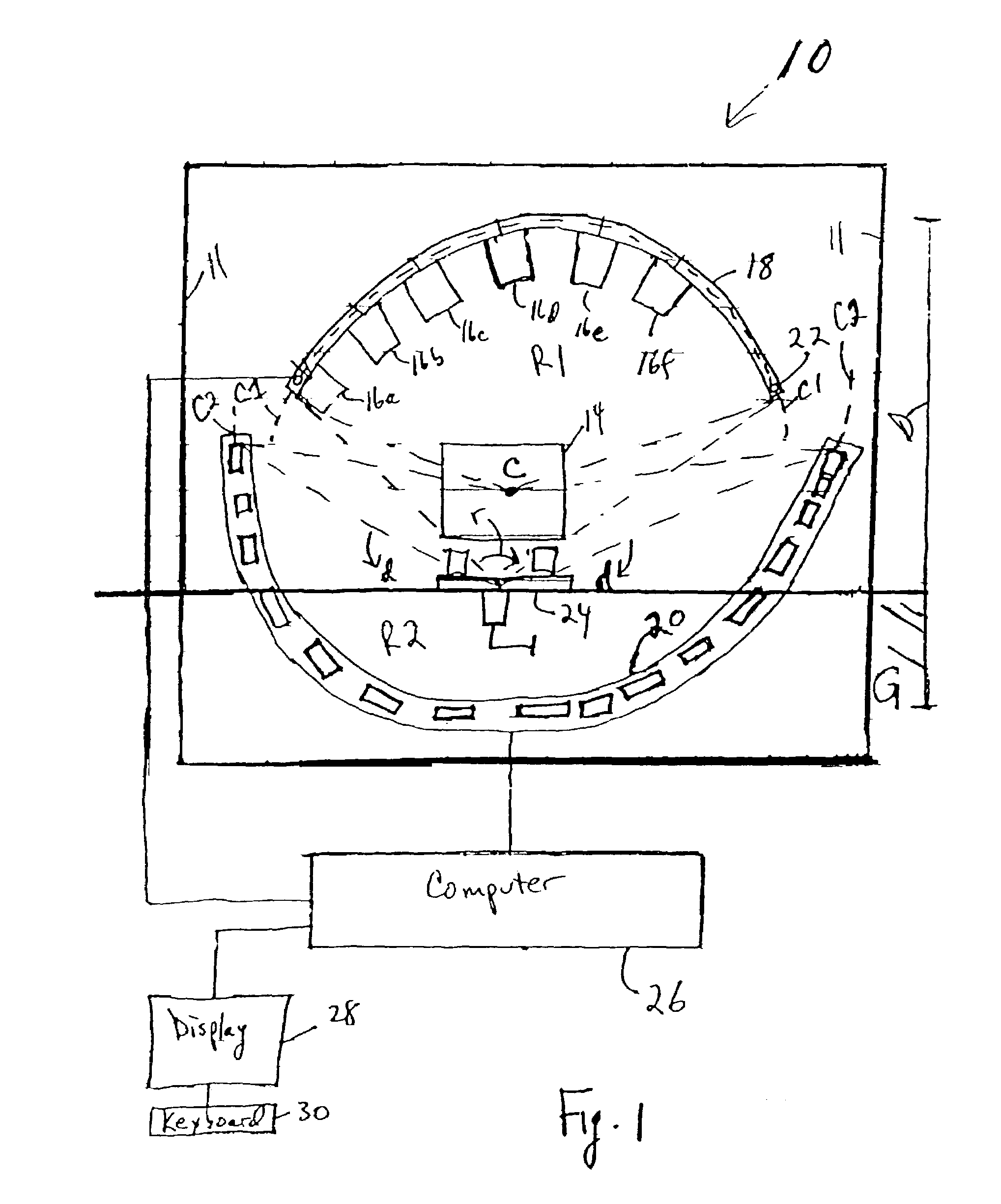
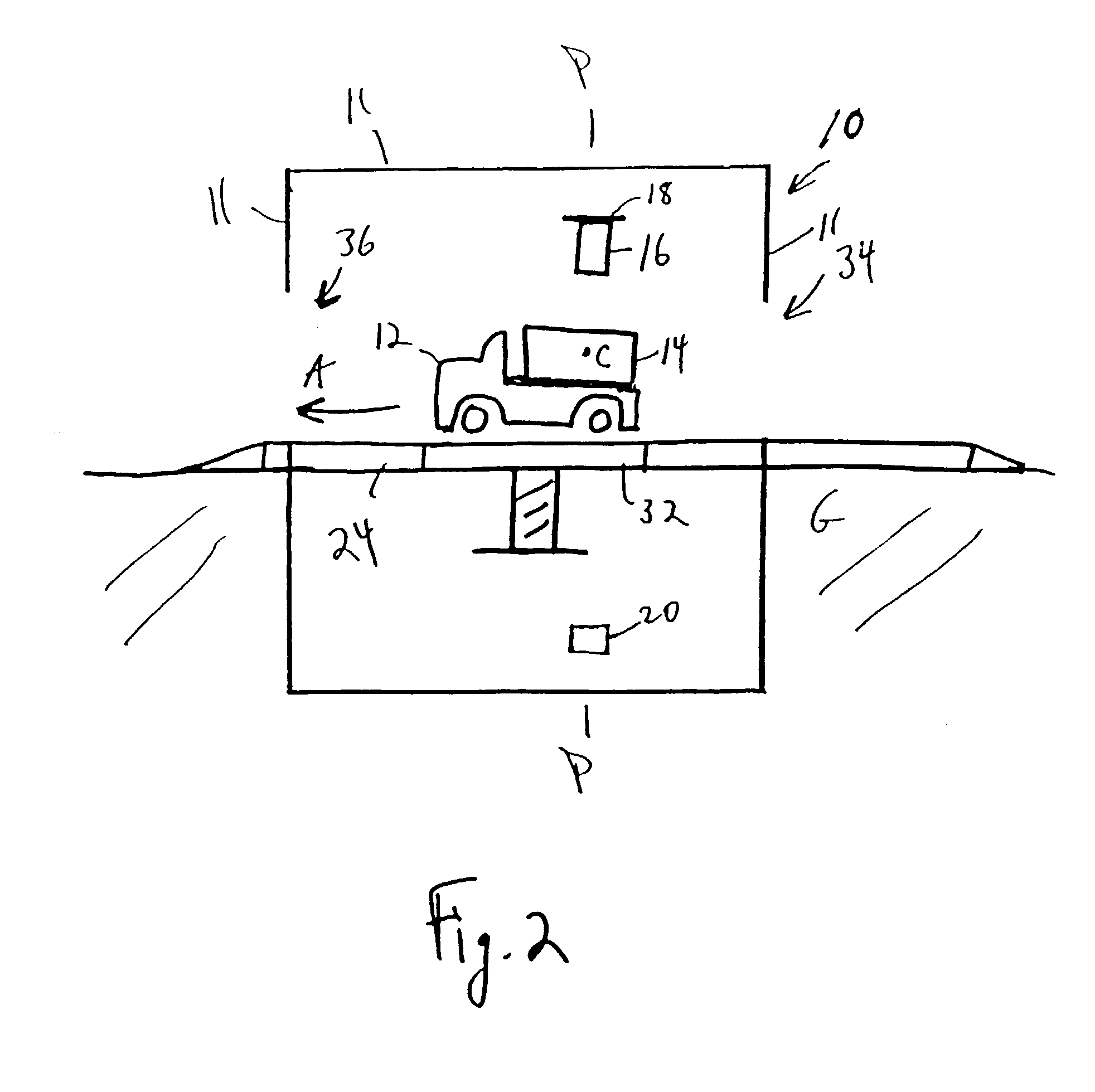
[0038]FIG. 1 is a front schematic view of an interior of a cargo scanning unit 10 for inspecting objects for contraband, such as explosive devices and materials, in accordance with one embodiment of the invention. FIG. 2 is a side schematic view of the center of the interior of the cargo scanning unit 10. The objects can be small objects, such as luggage and bags, or large objects, such as cargo containers. The scanning unit 10 comprises shielded walls 11. In FIG. 1, a truck 12 carrying a cargo container 14 is shown moving through the scanning unit 10, out of the page, along a first path. In FIG. 2, the direction of the first path is indicated by arrow “A”.

[0039]In this embodiment, the scanning unit 10 comprises six X-ray sources 16a–16f, a rail 18 supporting each of the X-ray sources 16a–16f and a detector 20. The detector 20 may be a detector array comprising a plurality of detector modules 21, as shown in FIG. 3, for example. The rail 18 and the detector array 20 lie along the sa...


PUM


Abstract

A scanning unit for identifying contraband within objects, such as cargo containers and luggage, moving through the unit along a first path comprises at least one source of a beam of radiation movable across a second path that is transverse to the first path and extends partially around the first path. A stationary detector transverse to the first path also extends partially around the first path, positioned to detect radiation transmitted through the object during scanning. In one example, a plurality of movable X-ray sources are supported by a semi-circular rail perpendicular to the first path and the detector, which may be a detector array is also semi-circular and perpendicular to the path. A fan beam may also be used. Radiographic images may be obtained and/or computed tomography (“CT”) images may be reconstructed. The images may be analyzed for contraband. Methods of scanning objects are also disclosed.

Description

FIELD OF THE INVENTION[0001]Radiation scanning of objects, including large objects such as cargo containers, to identify contraband.BACKGROUND OF THE INVENTION[0002]Radiation is commonly used in the non-invasive inspection of objects such as luggage, bags, briefcases and the like, to identify hidden contraband at airports and public buildings. The contraband may include hidden guns, knives, explosive devices and illegal drugs, for example. One common inspection system is a line scanner, where the object to be inspected is passed between a stationary source of radiation, such as X-ray radiation, and a stationary detector. The radiation is collimated into a fan beam or a pencil beam. Radiation transmitted through the object is attenuated to varying degrees by the contents of the luggage. The attenuation of the radiation is a function of the density of the materials through which the radiation beam passes. The attenuated radiation is detected and radiographic images of the contents of ...

Claims


Application Information

Patent Timeline
IPC IPC(8): G01N23/00G01N23/04G01T1/29G01V5/00
CPCG01N23/04G01V5/005G01T1/2985G01N2223/423
Inventor SEPPI, EDWARD J.MARC, MARCELFORD, JOHN
Owner VAREX IMAGING CORP
Why Eureka
Try Eureka