Extended range image processing for electro-optical systems

an electro-optical system and image processing technology, applied in the field of image processing, can solve the problems of reducing the ability of a viewer to perceive, and limited resolution of the sensor used, etc., and achieve the effect of improving the snr

Inactive Publication Date: 2006-09-05
LOCKHEED MARTIN CORP
View PDF48 Cites 12 Cited by
  • Summary
  • Abstract
  • Description
  • Claims
  • Application Information

AI Technical Summary

Problems solved by technology

In conventional EO systems, the sensors used are limited in their resolution by the fixed spacing between sensor elements.
A similar type of distortion can arise in, for example, a scene containing edge transitions which are so close together that a sensor cannot accurately resolve them.
Resultant distortion can manifest itself as color fringes, in a color camera, around an edge or the like, reducing the ability of a viewer to perceive, for example, letters or object outlines with clarity.
Range performance of an EO sensor is also often limited by the Nyquist frequency of the sensor, particularly those containing staring focal-plane arrays.
In addition, sensor range can be limited by distortion levels or noise associated with sensor construction.
These types of improvements, however, increase the cost and size of the system, which can lead to a design that is too costly or too large to fit the application.
However, dither mechanisms, such as a FSM, are usually very expensive and are sensitive to vibrations and alignment.

Method used


Image

  • Extended range image processing for electro-optical systems
  • Extended range image processing for electro-optical systems
  • Extended range image processing for electro-optical systems

Examples


Embodiment Construction

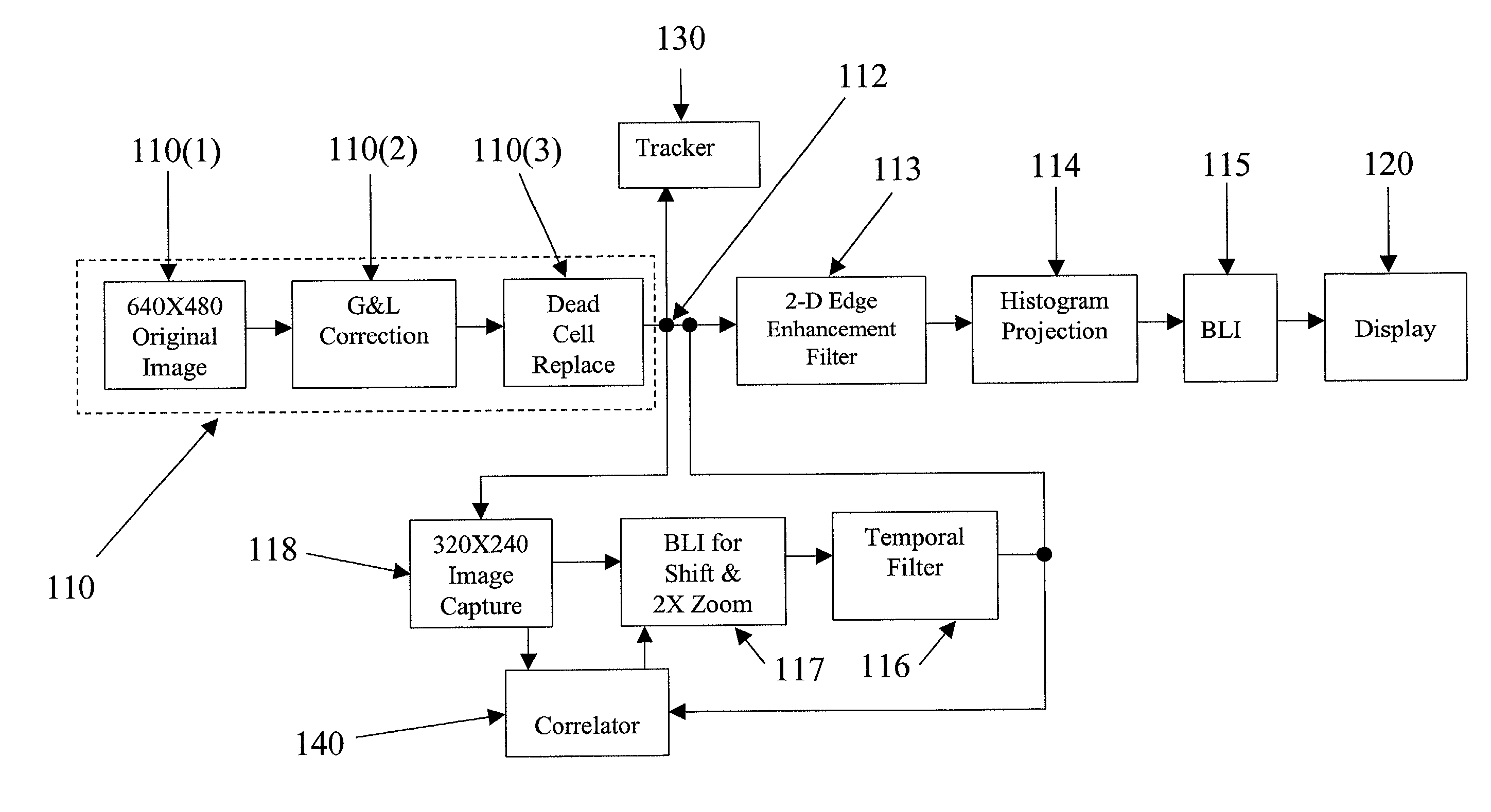
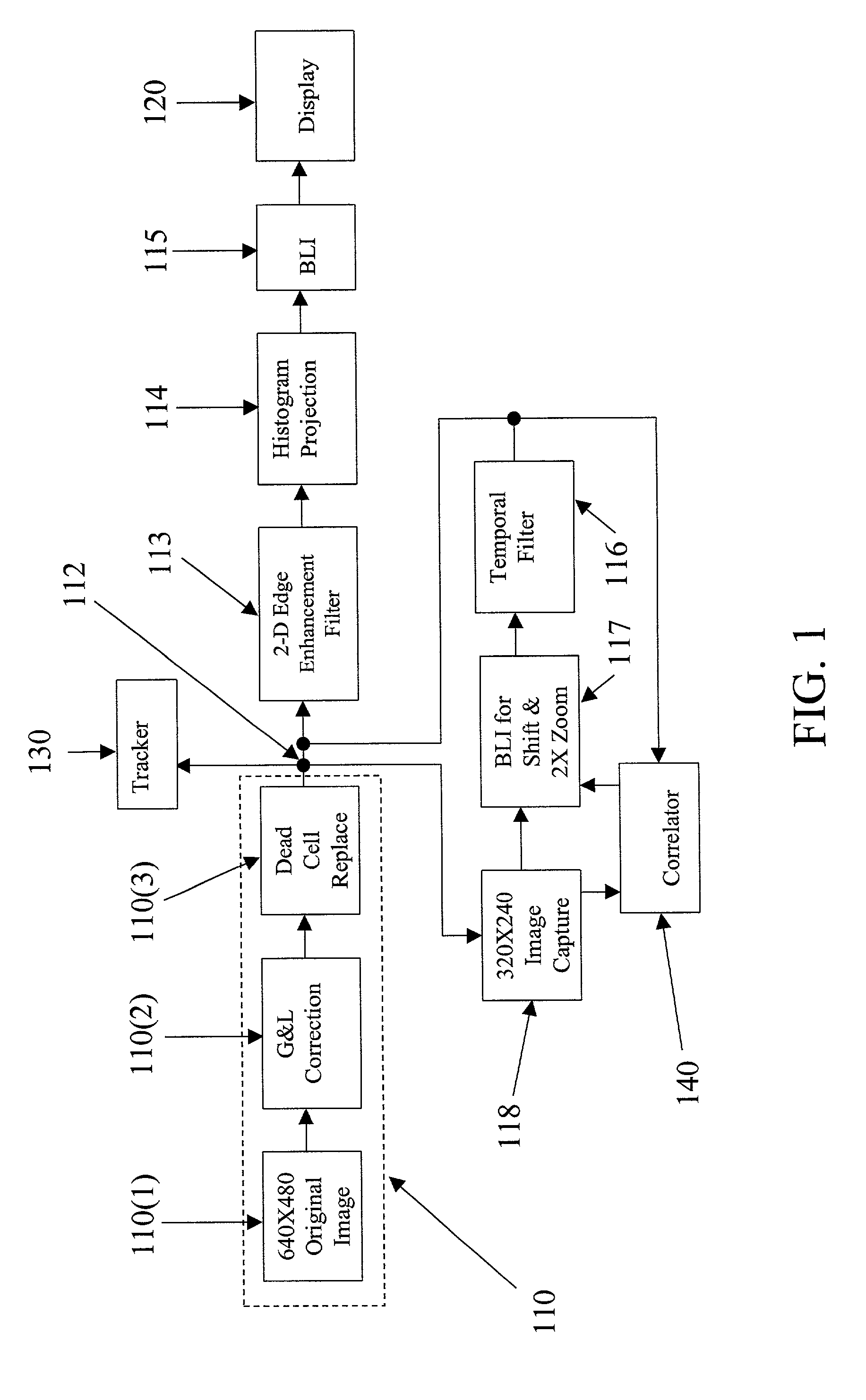
[0024]FIG. 1 is a functional block diagram of a system 100 for processing imagery, such as digital imagery, using an Electro-Optical (EO) system in accordance with an exemplary embodiment of the present invention. Image acquisition can be initiated by an operator or, for example, during target track. Initially, a first frame of data can be selected as a template frame, in any desired fashion. For example, the template frame can be selected from a database of possible templates, or can be captured using the EO system, or any other image source.

[0025]In the FIG. 1 embodiment, an image storage device 110 can store an image, referred to herein as an original image 110(1), in any known manner. The original image 110(1) can be a pre-stored frame of image data or image data acquired in any manner known in the art, from any of a variety of EO systems or sensors including, but not limited to, a thermal sensor, imaging radar sensor, infrared sensor or the like, or from, for example, the Field...


PUM


Abstract

A method and apparatus for processing imagery using images acquired via any known Electro-Optical (EO) system. In accordance with exemplary embodiments of the present invention, a first frame of data is selected as a template frame (e.g., a given frame). A second frame of data can be captured using the EO system. At least a portion of the second frame can be correlated with the template frame to generate a shift vector. The second frame can then be registered with the template frame by interpolating the second frame using the shift vector and re-sampling at least a portion of the second frame to produce a registered frame. The template frame can also be re-sampled. The registered frame and the re-sampled template frame can then be combined to generate an averaged frame. The averaged frame can be spatially filtered to enhance edges within the averaged frame.

Description

CROSS REFERENCE TO RELATED APPLICATION[0001]The present application is related to U.S. patent application entitled “Scene-Based Non-Uniformity Correction for Detector Arrays”, Ser. No. 09 / 840,920, and to U.S. patent application entitled “Dynamic Range Compression”, Ser. No. 09 / 841,081, both filed even date herewith.BACKGROUND[0002]1. Field of the Invention[0003]The present invention relates to image processing. More particularly, the present invention relates to processing image data using images acquired via Electro-Optical (EO) systems.[0004]2. Background Information[0005]EO systems are often used for “remote sensing.” The term “remote sensing” generally refers to the acquisition and measurement of data / information related to one or more properties of a phenomenon, object, or material by a recording device not in physical contact with the object under surveillance. Imaging techniques often involve gathering information by measuring electromagnetic fields, electromagnetic radiation...

Claims


Application Information

Patent Timeline
Patent Type & Authority Patents(United States)
IPC IPC(8): G06K9/32G06T5/20G06T5/50H04N5/217H04N5/265H04N5/33H04N5/365H04N5/372
CPCG06T5/20H04N5/2176G06T5/50H04N5/33H04N25/63
Inventor TENER, GENE D.BENTON, SR., RICHARD W.ALDERSON, TIMOTHY
Owner LOCKHEED MARTIN CORP
Why Eureka
Try Eureka