Camera which records positional data of GPS unit
- Summary
- Abstract
- Description
- Claims
- Application Information
AI Technical Summary
Benefits of technology
Problems solved by technology
Method used
Image
Examples
first embodiment
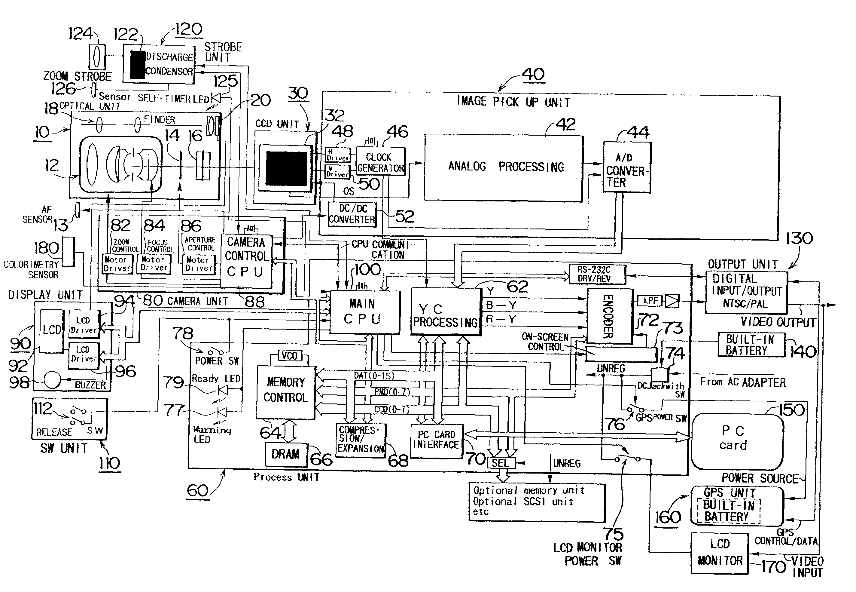
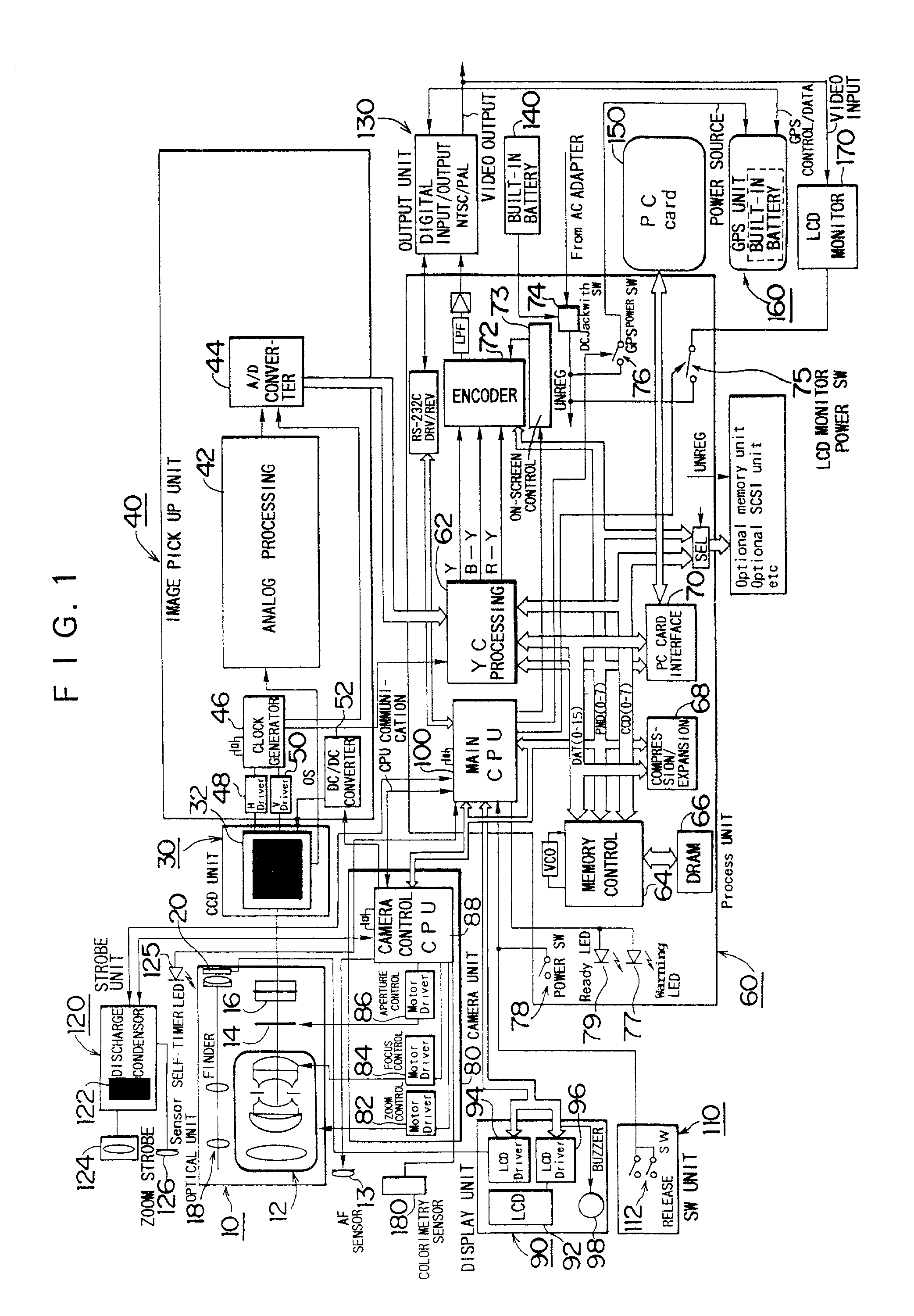
[0046]FIG. 1 is a block diagram illustrating an electronic camera according to the present invention. This electronic camera includes an optical unit 10, a CCD unit 30, an image pickup unit 40, a process unit 60, a camera unit 80, a display unit 90, a switch (SW) unit 110, a strobe unit 120, an output unit 130, and a GPS unit 160.
[0047]The optical unit 10 has a taking lens 12 comprising a focus lens and a variable magnification lens, a diaphragm 14, and an optical low pass filter (LPF) 16. An image light of a subject is formed on a light receiving surface of a CCD sensor 32 of the CCD unit 30 through the taking lens 12, the diaphragm 14 and the optical LPF 16. The zoom lens and the focus lens of the taking lens 12 are moved by a zoom motor driver 82 and a focus motor driver 84, which are controlled by a camera control CPU 88 of the camera unit 80. Thereby, the zooming magnification and the focus can be adjusted. The aperture of the diaphragm 14 is adjusted by an aperture motor drive...
second embodiment
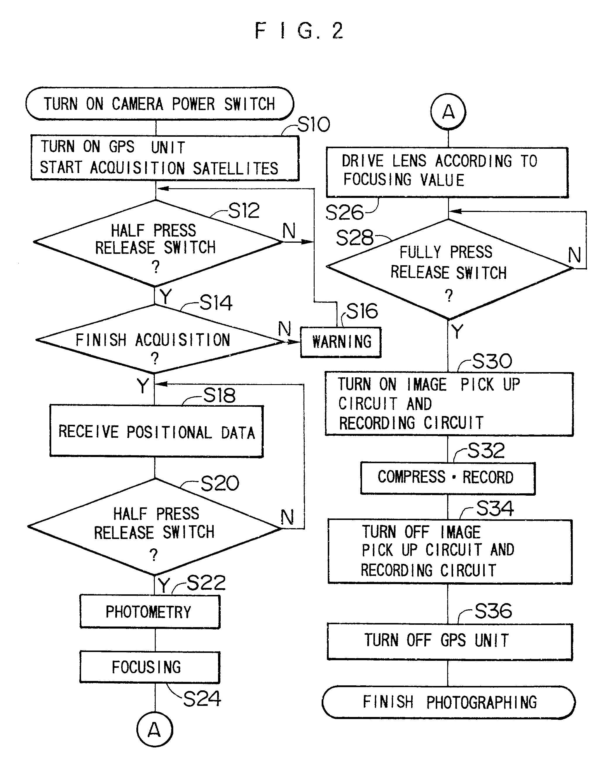
[0078]FIG. 3 is a flow chart illustrating the control procedure of the main CPU 100. In this embodiment, the positional data of the GPS unit 160 is received after the release switch 112 is half pressed, and the image-capturing is allowed (when the release switch 112 is fully pressed) after the positional data is received.
[0079]When the camera power switch 78 is turned on, the main CPU 100 turns on the GPS power switch 76 to supply the GPS unit 160 with electricity to make the GPS unit 160 start acquiring the satellites (S50). In this case, the main CPU 100 does not supply electricity to the image pickup circuit and the recording circuit.
[0080]Then, the main CPU 100 monitors the release switch 112 to decide whether the release switch 112 is half pressed or not (S52). When the main CPU 100 detects that the release switch 112 is half pressed, the photometry is performed to obtain a photometry value (S54), and the focusing is performed to obtain a focusing value (S56). Then, the lens of...
third embodiment
[0085]FIG. 4 is a flow chart illustrating the control procedure of the main CPU 100. In this embodiment, the positional data of the GPS unit 160 is received after the release switch 112 is fully pressed to complete the image-capturing.
[0086]When the camera power switch 78 is turned on, the main CPU 100 monitors the release switch 112 to decide whether the release switch 112 is half pressed or not (S80). In this case, the main CPU 100 does not supply electricity to the GPS unit 160, the image pickup circuit and the recording circuit.
[0087]If the release switch 112 is half pressed at S80, the main CPU 100 executes the photometry to obtain a photometry value (S82), and executes the focusing to obtain a focusing value (S84). Then, the lens of the taking lens 12 is driven to adjust the focus, etc. in accordance with the focusing value (S86).
[0088]Then, the main CPU 100 monitors the release switch 112 to decide whether the release switch 112 is fully pressed or not (S88). If the main CPU ...
PUM
 Abstract
Description
Claims
Application Information
 - R&D
- Intellectual Property
- Life Sciences
- Materials
- Tech Scout
- Unparalleled Data Quality
- Higher Quality Content
- 60% Fewer Hallucinations
Browse by: Latest US Patents, China's latest patents, Technical Efficacy Thesaurus, Application Domain, Technology Topic, Popular Technical Reports.
© 2025 PatSnap. All rights reserved.Legal|Privacy policy|Modern Slavery Act Transparency Statement|Sitemap|About US| Contact US: help@patsnap.com


