Safety network system

Inactive Publication Date: 2006-09-05
ORMON CORPORATION
View PDF13 Cites 7 Cited by
  • Summary
  • Abstract
  • Description
  • Claims
  • Application Information

AI Technical Summary

Benefits of technology

[0011]The present invention was made to solve the above problems and it is an object of the present invention not to lower the response time while the main device is switched from the operating state to the stopped state when any safety determining device detec

Problems solved by technology

However, since the amount of communication data is increased as the whole of the system, transmission of the safety check data is delayed and when any safety determining device d

Method used


Image

  • Safety network system
  • Safety network system
  • Safety network system

Examples


Example

[0049]Preferred embodiments of the present invention is described in detail with reference to the accompanying drawings hereinafter. In addition, it is needless to say that the present invention is not limited to the illustrated embodiments.

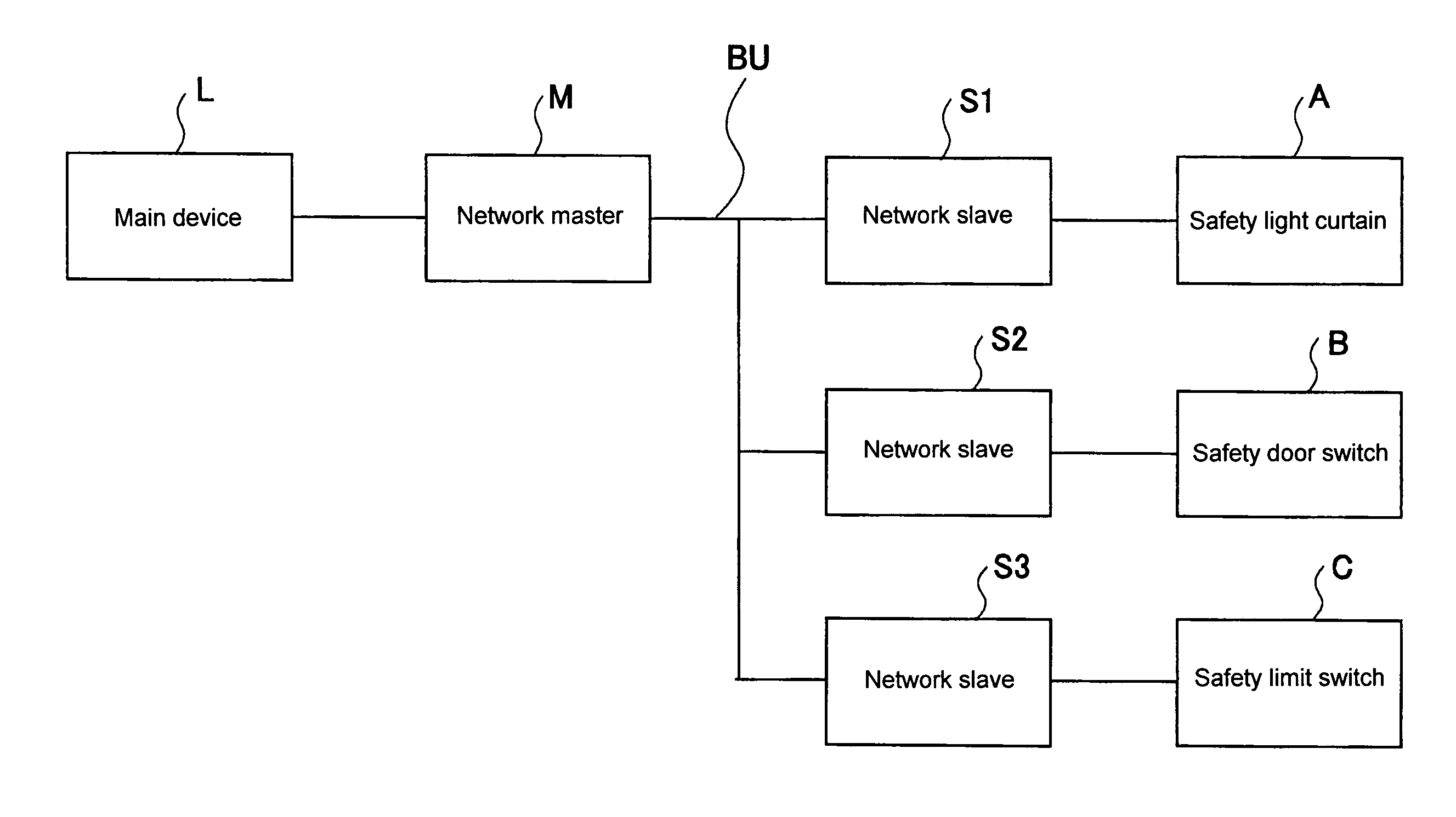
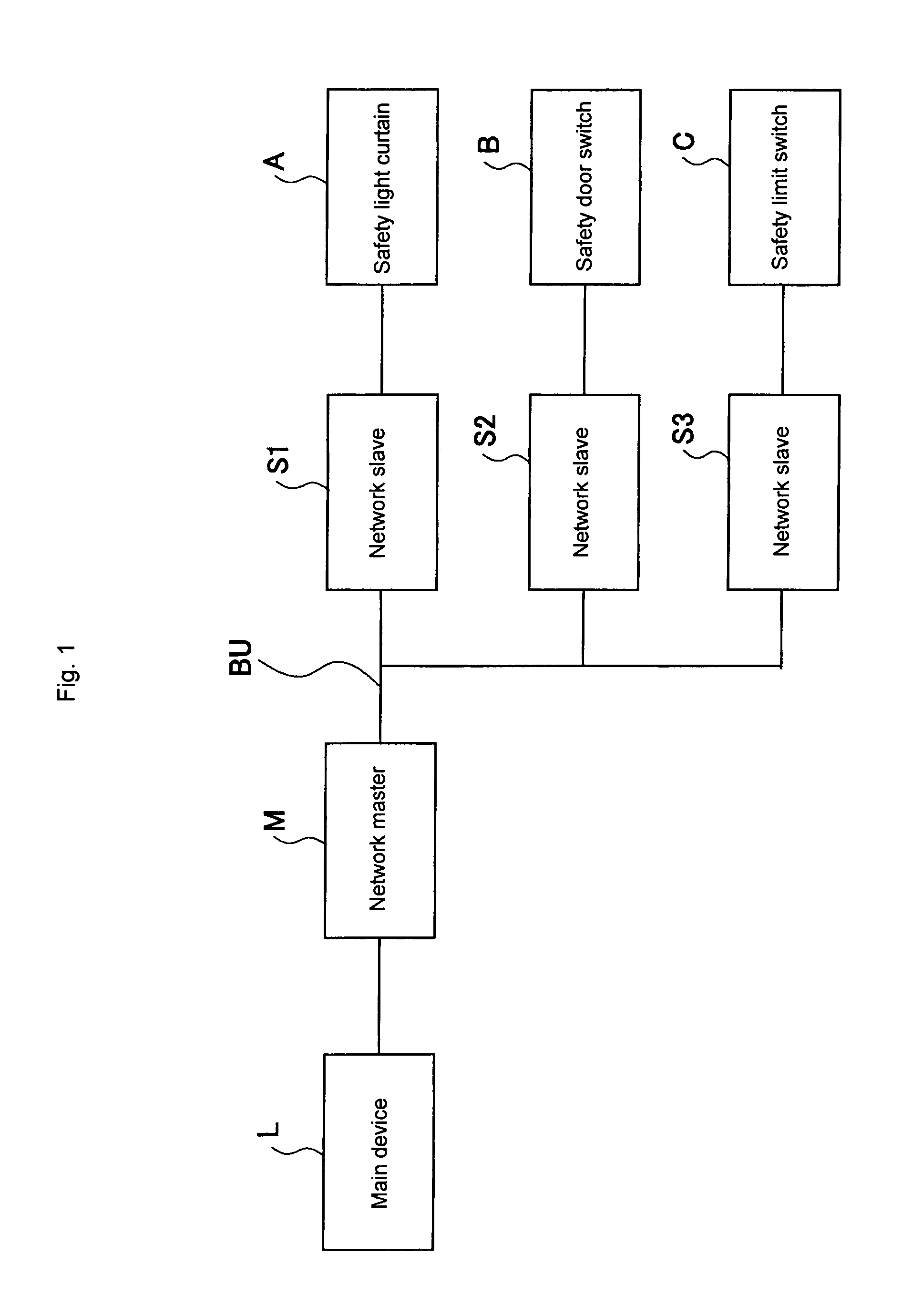
[0050]As described above, a safety network system according to the present invention comprises a network master having charge of an operation of a main device, one or more network slaves each having charge of a safety determining device for determining safety which is an operating permission condition of the main device, and the like which are connected on the network.

[0051]FIG. 1 is a block diagram showing a system according to the present invention. As shown in FIG. 1, this safety network system comprises a network master M, and three network slaves S1 to S3 which are connected by a serial bus BU constituting the network.

[0052]The network master M has charge of an operation of a main device L. The main device L corresponds to a pressing machine...


PUM


Abstract

A network master (M) having charge of an operation of a main device (L) and one or more network slaves (S1 to S3) each having charge of a safety determining device (A to C) for determining safety which is an operating permission condition of the main device (L) are connected on the network. Each network slave comprises means for selectively performing a first operation for transmitting information including data for maintenance of the safety determining device or both determination output of the safety determining device and data for maintenance of the safety determining device, to the network master and a second operation for transmitting information including the determination output of the safety determining device but not including the data for maintenance of the safety determining device at all or hardly including it to the network master. The first operation in the network slave is performed when the main device is in a stopped state and the second operation in the network slave is performed when the main device is in an operating state.

Description

[0001]This application is a National Stage application of PCT / JP02 / 05603, filed Jun. 6, 2002, which claims priority from Japanese patent application 2001-174770, filed Jun. 8, 2001. The entire contents of each of the aforementioned applications are incorporated herein by reference.BACKGROUND OF THE INVENTION[0002]1. Field of the Invention[0003]The present invention relates to a safety network system for organically connecting a main device such as a machine tool or the like in which operation safety measure is required, to a plurality of safety determining devices such as safety light curtains or the like which determine an operation safety condition or the like, and more particularly, it relates to a safety network system having high reliability in which aged deterioration of a safety determining device itself or the like can be appropriately managed without lowering responsibility of stopping a main device when a danger condition occurs.[0004]2. Description of the Prior Art[0005]I...

Claims


Application Information

Patent Timeline
IPC IPC(8): G05B11/01G05B9/02
CPCG05B9/02
Inventor TAKEUCHI, HISASHISHIMOKAWA, SATORUKAWAIKE, NOBORU
Owner ORMON CORPORATION
Why Eureka
Try Eureka