Method and apparatus for achieving temperature uniformity and hot spot cooling in a heat producing device

a heat producing device and temperature uniformity technology, applied in the direction of power cables, cables, instruments, etc., can solve the problems of multiple hot spots, unoptimized cooling, and parallel channel arrangements which are not optimally suited for cooling, and achieve the effect of minimizing temperature differences

Active Publication Date: 2006-09-12
VERTIV CORP
View PDF245 Cites 162 Cited by
  • Summary
  • Abstract
  • Description
  • Claims
  • Application Information

AI Technical Summary

Benefits of technology

[0007]One aspect of the invention is directed to a method of controlling temperature of a heat source in contact with a heat exchanging surface of a heat exchanger, wherein the heat exchanging surface is substantially aligned along a plane. The method comprises channeling a first temperature fluid to the heat exchanging surface, wherein the first temperature fluid undergoes thermal exchange with the heat source along the heat exchanging surface. The method comprises channeling a second temperature fluid from the heat exchange surface, wherein fluid is channeled to minimize temperature differences along the heat source.

Problems solved by technology

However, existing microchannels include conventional parallel channel arrangements which are not optimally suited for cooling heat producing devices which have spatially-varying heat loads.
In addition, a substantially varying heat flux across the surface of the heat source can induce temperature differences along the heat source surface, thereby forming multiple hot spots.
Prior art heat exchangers only focus on cooling the heat source and thereby do not focus on the aspects of hot spot cooling or overall temperature uniformity.

Method used


Image

  • Method and apparatus for achieving temperature uniformity and hot spot cooling in a heat producing device
  • Method and apparatus for achieving temperature uniformity and hot spot cooling in a heat producing device
  • Method and apparatus for achieving temperature uniformity and hot spot cooling in a heat producing device

Examples


Embodiment Construction

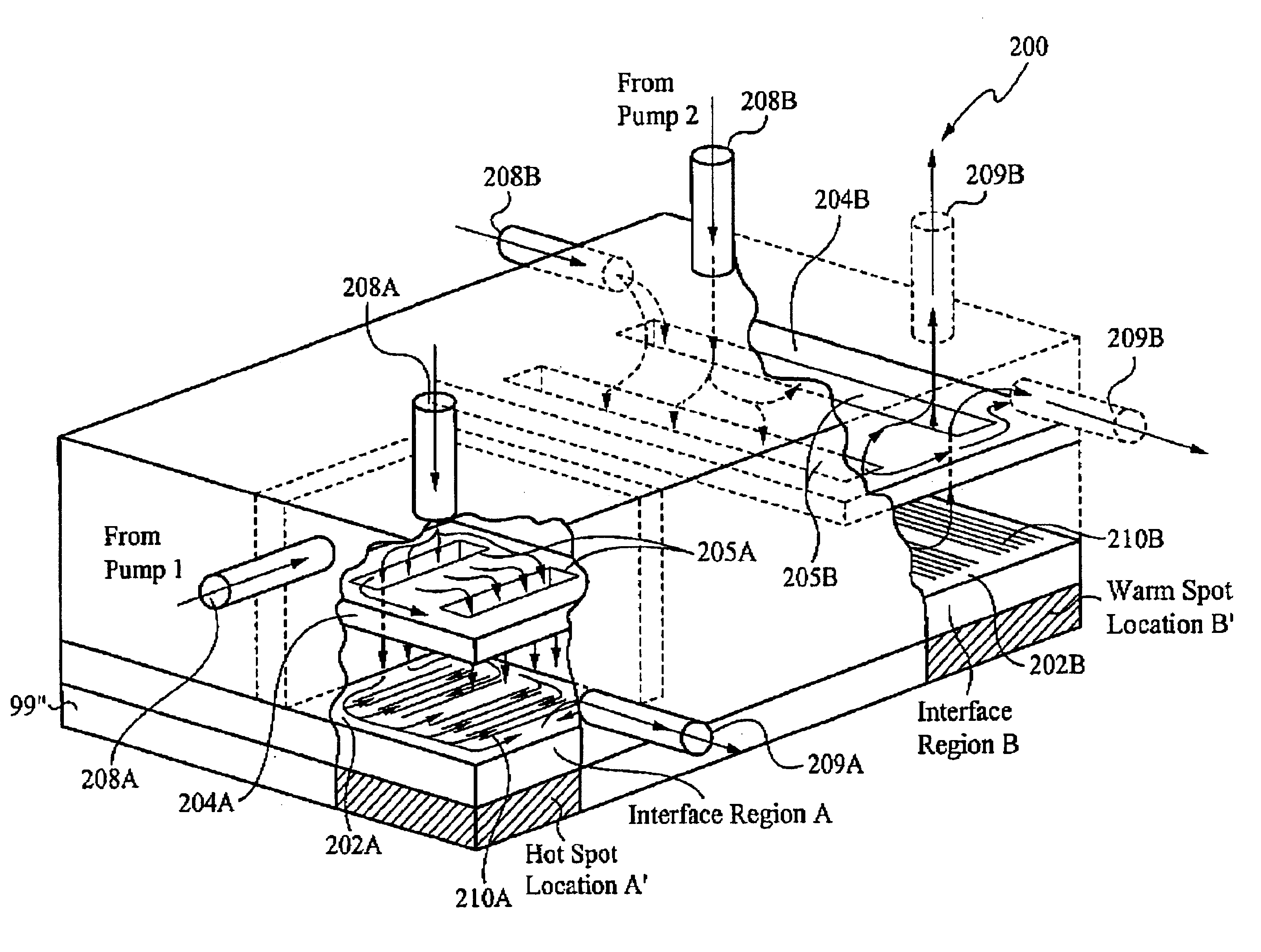
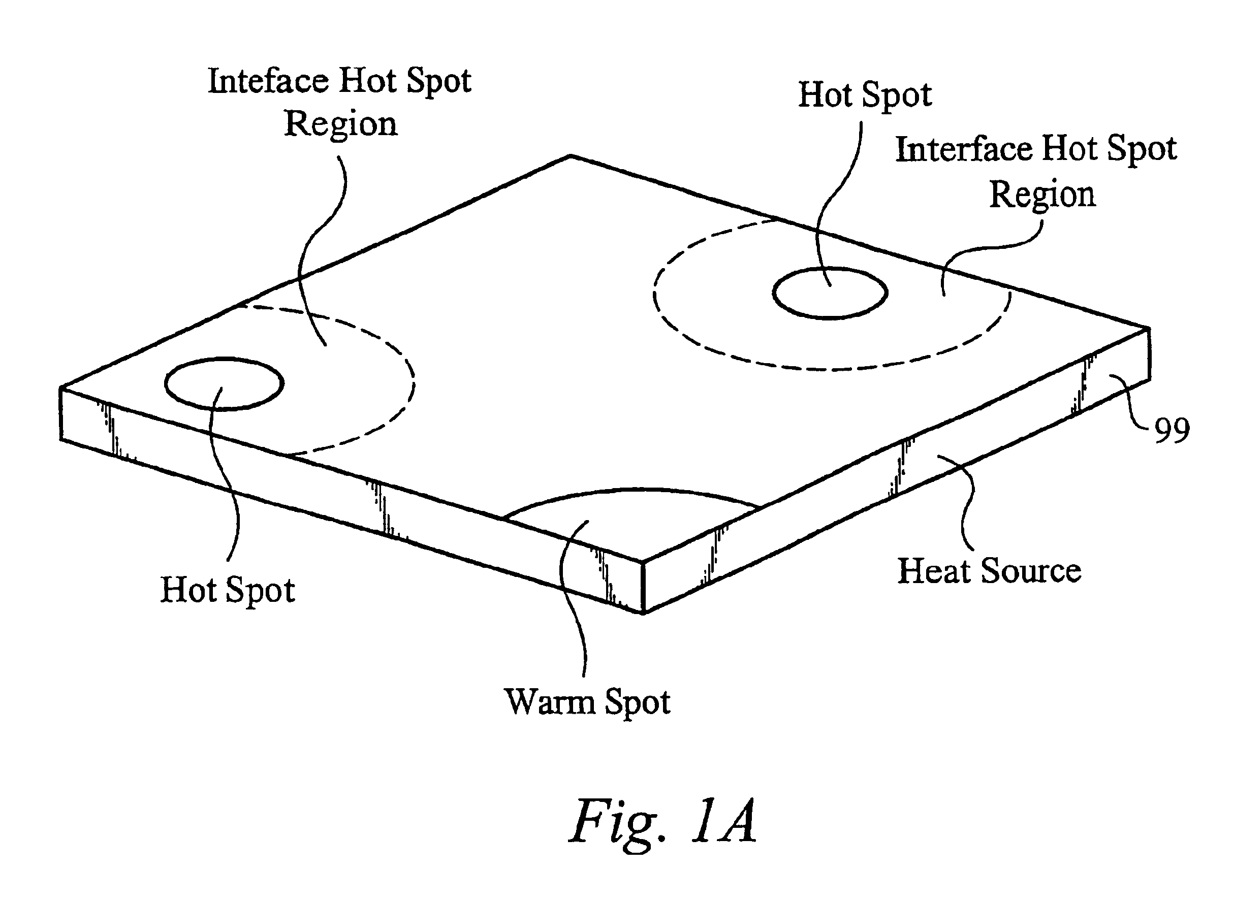
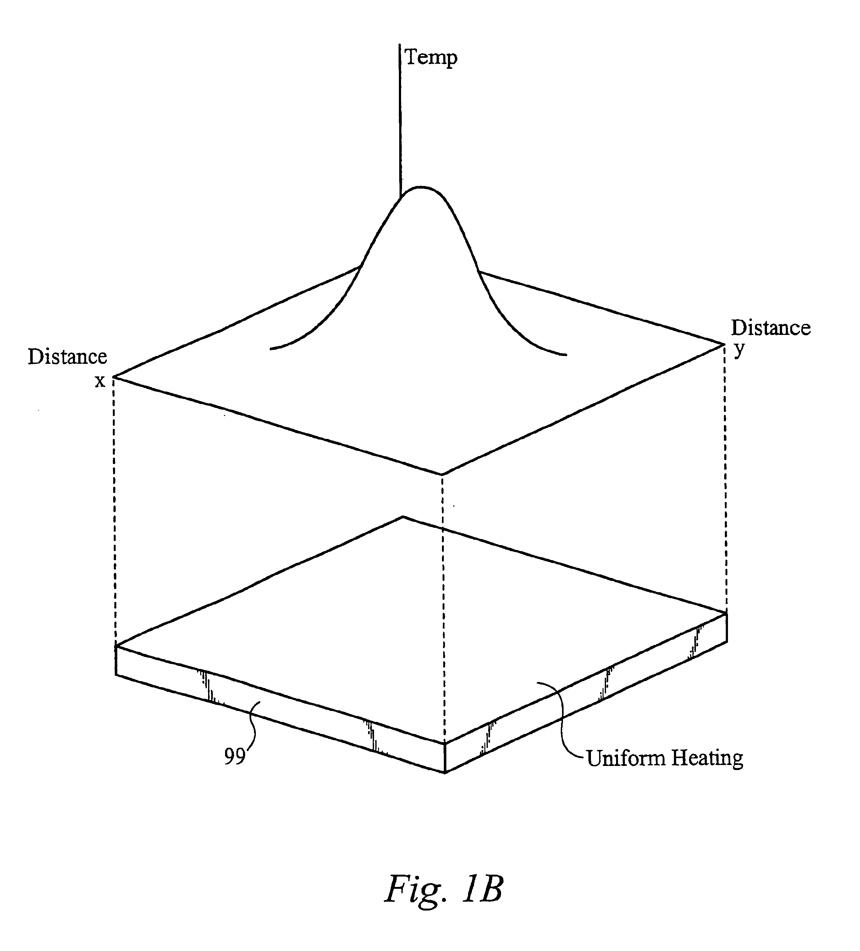
[0031]Generally, a closed-loop fluid system according to the present invention operating in conjunction with a heat exchanger to capture thermal energy generated from a heat source by passing fluid through selective areas of the interface layer in contact with the heat source. In particular, the fluid can be directed in one or two phase flow to specific areas in the interface layer to cool hot spots and / or to reduce temperature differences across the heat source while maintaining an optimal pressure drop within the heat exchanger. In addition, achieving temperature uniformity encompasses minimizing temperature gradients that occur automatically in any heat source. In addition, achieving temperature uniformity in the heat source encompasses minimizing temperature gradients in the absence of hot spots, as in FIG. 1B. Therefore, achieving temperature uniformity includes reducing temperatures differences between the hotter areas, warmer areas and cooler areas in the heat source. As disc...


PUM

PropertyMeasurementUnit
porosityaaaaaaaaaa
pore sizeaaaaaaaaaa
thicknessaaaaaaaaaa

Abstract

A method of controlling temperature of a heat source in contact with a heat exchanging surface of a heat exchanger, wherein the heat exchanging surface is substantially aligned along a plane. The method comprises channeling a first temperature fluid to the heat exchanging surface, wherein the first temperature fluid undergoes thermal exchange with the heat source along the heat exchanging surface. The method comprises channeling a second temperature fluid from the heat exchange surface, wherein fluid is channeled to minimize temperature differences along the heat source. The temperature differences are minimized by optimizing and controlling the fluidic and thermal resistances in the heat exchanger. The resistances to the fluid are influenced by size, volume and surface area of heat transferring features, multiple pumps, fixed and variable valves and flow impedance elements in the fluid path, pressure and flow rate control of the fluid, and other factors.

Description

RELATED APPLICATIONS[0001]This patent application claims priority under 35 U.S.C. 119(e) of the co-pending U.S. Provisional Patent Application, Ser. No. 60 / 462,245, filed Apr. 11, 2003 and entitled “RING STIFFENER PROTECTOR AND REMOVEABLE SPREADER LID”, which is hereby incorporated by reference. This patent application also claims priority under 35 U.S.C. 119(e) of the co-pending U.S. Provisional Patent Application, Ser. No. 60 / 423,009, filed Nov. 1, 2002 and entitled “METHODS FOR FLEXIBLE FLUID DELIVERY AND HOTSPOT COOLING BY MICROCHANNEL HEAT SINKS”, which is hereby incorporated by reference. In addition, this patent application claims priority under 35 U.S.C. 119(e) of co-pending U.S. Provisional Patent Application, Ser. No. 60 / 442,383, filed Jan. 24, 2003 and entitled “OPTIMIZED PLATE FIN HEAT EXCHANGER FOR CPU COOLING”, which is hereby incorporated by reference. Additionally, this application claims priority under 35 U.S.C. 119(e) of co-pending U.S. Provisional Patent Applicati...

Claims


Application Information

Patent Timeline
Patent Type & Authority Patents(United States)
IPC IPC(8): F28F7/00B21D53/02F04B19/00F28F13/18F28F19/02G05D23/00H01L23/427H01L23/473
CPCF04B19/006F28D15/00F28F3/048F28F3/12F28F2260/02Y10T29/4935H01L23/473H01L2924/0002H01L23/427H01L2924/00
Inventor GOODSON, KENNETHKENNY, THOMASZHOU, PENGUPADHYA, GIRISHMUNCH, MARKMCMASTER, MARKHORN, JAMES
Owner VERTIV CORP
Why Eureka
Try Eureka