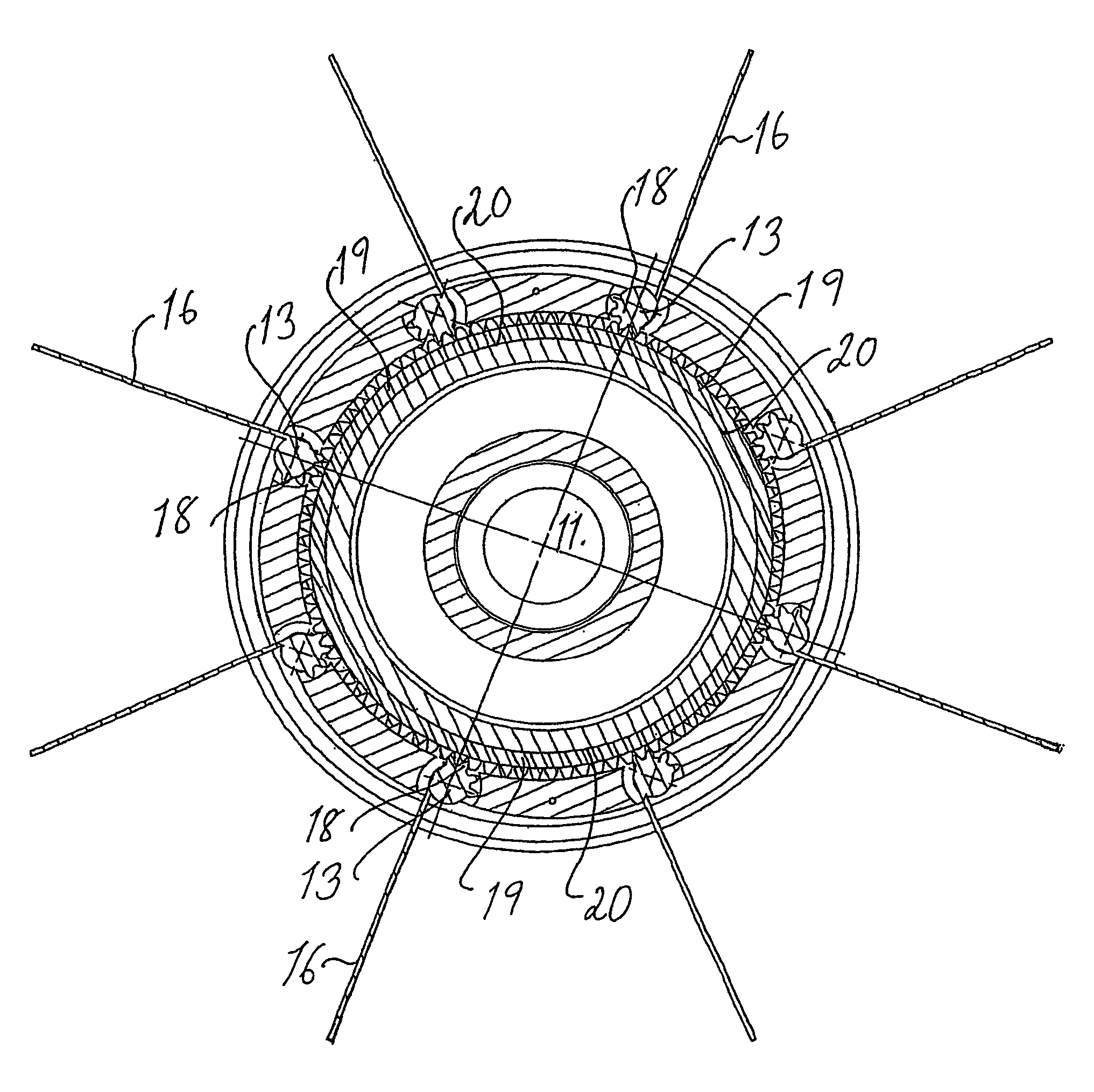
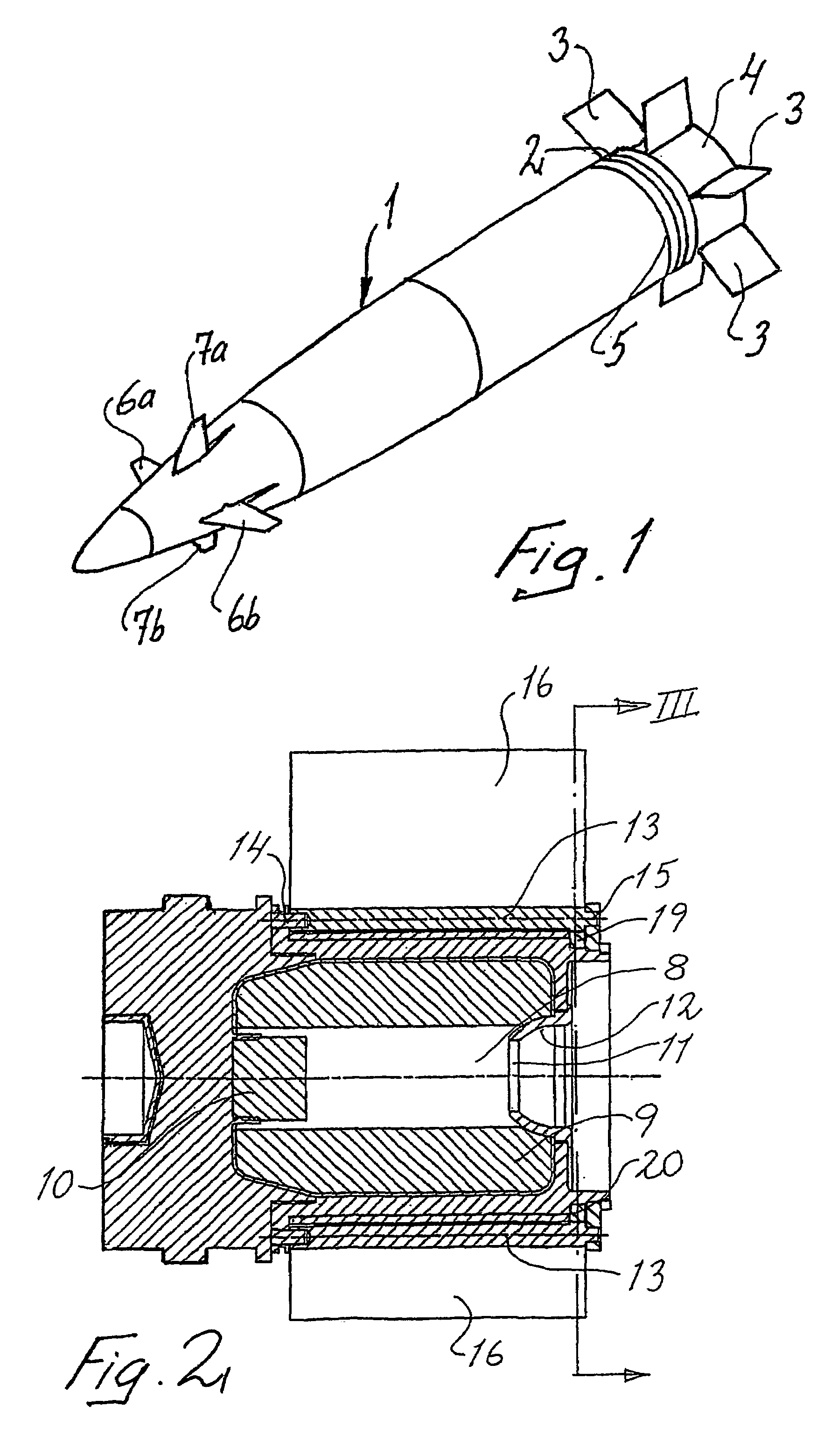
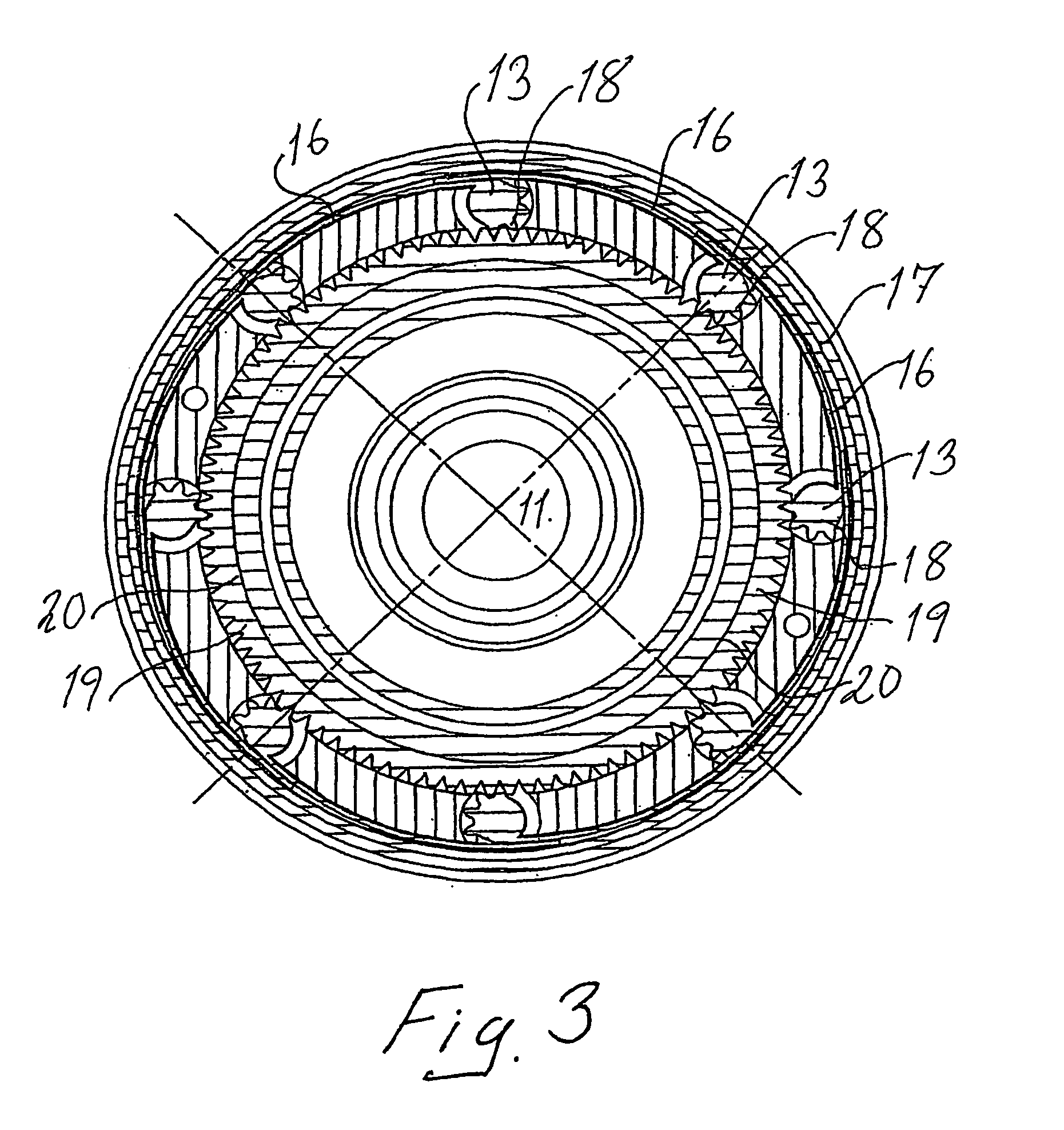
[0010]Accordingly, the object of the present invention is to eliminate, in a reliable manner, the effects of an otherwise readily occurring incomplete fin fold-out, and this is achieved by fold-out of the fins in relation to one another being synchronized using means adapted thereto. According to the invention, the fins are therefore to be interconnected in such a manner in relation to one another that they are folded out at the same speed. The invention therefore concerns a method of forcing the fins most heavily loaded in the fold-out direction to share the fold-out force acting on them with fins which are more lightly loaded in the fold-out direction at the same time as the latter are to force the more heavily loaded fins to slow down their fold-out speed and thus also to reduce the risk of them being overloaded. The basic principle of the invention is therefore that all the fins are to be connected by means of a common fin fold-out control or
synchronizing arrangement which is to be designed in such a manner that it gives all the fins a simultaneously initiated uniform fold-out at the same speed from their initial folded-in position with that part of the fin blade or the active area of the fin which lies closest to the spindle extending tangentially to the immediately adjacent outer side of the shell into a folded-out position in which the fin blades are angled at in principle 90° relative to the folded-in position, in which position the fin blades or the active areas of the fins extend radially out from the shell body. The invention also includes the fact that the fins should, via the
synchronizing arrangement, help one another with fold-out or alternatively
brake one another as required. A direct drive function is therefore, at least in the first place, not intended to be included in the
system. An essential part of fin fold-out is also that the fin plates which constitute the active areas of the fins recover elastically from their incurvation towards the shell body to the finally intended shape they were once given. Another
advantage of the invention is that, in an especially preferred embodiment, it requires very limited extra space and by virtue of this makes it possible to arrange both the fold-out fins and a base-bleed unit within the same part of the shell.
[0011]The invention therefore provides a method and an arrangement which guarantee that the fold-out fins on an
artillery shell with a sliding driving band fired from a rifled barrel achieve their completely folded-out and locked end position. It is characteristic of the method and the arrangement according to the invention in this connection that any form of non-uniform fin fold-out and associated negative influence on the flight of the shell will be avoided by virtue of all the guide fins being interconnected by means adapted thereto to form a
system which, during the fold-out phase, gives the fins a synchronized
movement pattern with simultaneous and uniform fold-out movements.
[0012]In order to make it possible to perform such a synchronized fin fold-out function, we have introduced a movement transmission means which connects all the rotation spindles around which the fins have, during the firing phase, been curved in towards the shell body, in which position they have been retained by a special protective cover from the completion of the shell during manufacture until it leaves the mouth of the barrel. When the shell leaves the mouth of the barrel, the protective cover is torn away from the shell by an inner
powder gas pressure which, during the firing phase, is allowed to leak into the cover and which, inside the barrel, is balanced by the
powder gas pressure behind the shell. This is because, when the shell leaves the barrel, this counterpressure ceases very rapidly and, by
dimensioning the
gas supply to the cover so that it is not possible for its inner
overpressure to be eliminated at the same rate as the abrupt reduction in pressure behind the shell takes place, the cover will be thrown off.
[0013]As soon as the protective cover has been removed, fin fold-out will begin and, as the method and the arrangement according to the invention are primarily intended for use on shells with sliding driving bands, there is only at the very most a weak
centrifugal force available to assist fin fold-out. The majority of the force necessary for fin fold-out therefore has to be obtained, as already mentioned, from the straightening force built into the fins and also, to some extent, from the
relative wind force against the fins of the passing air. The object of the method and the arrangement according to the invention is therefore to even out this non-uniformity and to give all the fins the same fold-out speed.
[0014]According to an especially preferred embodiment, the main means of synchronizing the fin fold-out function consists of a control ring which is arranged concentrically around the longitudinal axis of the shell close to its outer wall, can rotate in a groove adapted thereto and connects the various fin spindles and gives these and the active areas of the fins identical movement patterns. In its most developed form, the outer surface of the control ring is designed as a toothed ring and each fin spindle is in turn provided with a corresponding toothed segment covering at least a quarter of a turn. Under certain circumstances, it would probably be possible to replace the toothing with low-cost variants in the form of
knurling or another friction-increasing treatment of the outer surface of the control ring and the rotation spindles of the fins. Another possible but, because it would result in so many small parts, less practical solution would be to use a number of links which interconnect cranks rigidly connected to respective spindles.


