Thrust reverser with sliding pivot joints

a technology of thrust reverser and pivot joint, which is applied in the direction of arrester hooks, marine propulsion, vessel construction, etc., can solve the problems of increased complication and cost, and increased weight of four-bar link system, so as to improve the reverse thrust and save weight. , the effect of improving the reverse thrus

Inactive Publication Date: 2006-09-12
AIRCRAFT INTEGRATION RESOURCES
View PDF15 Cites 22 Cited by
  • Summary
  • Abstract
  • Description
  • Claims
  • Application Information

AI Technical Summary

Benefits of technology

[0010]To solve the aforementioned and other problems, a thrust reverser in accordance with the present invention preferably comprises a plurality of doors mounted to pivot joints near the aft portions of the doors. Link rods, which may be pivoting, folding, or extensible, are provided near the forward portions of the doors. An actuator is preferably provided between each door, and slider rods on each actuator are connected to the pivot joint of the door on either side of the actuator. In the stowed position, the doors are located about the periphery of the engine exhaust nozzle out of the exhaust stream. To deploy the thrust reverser, the actuators cause the pivot joints to translate linearly aft, and the forward link rods cause the doors to rotate about the pivot joints. In the fully deployed position, the doors are located aft of the engine exhaust nozzle and substantially in the path of the exhaust stream. In this manner, the doors are able to reverse the flow of substantially the entire exhaust stream, including both core exhaust and bypass fan exhaust, which provides significantly improved reverse thrust. Because the present thrust reverser eliminates the rear bars of a conventional four-bar link system, the present thrust reverser provides significant weight savings, simpler operation, and increased reliability. Additionally, by keeping the rear pivot joints close to the mid-line of the engine, the present thrust reverser minimizes the distance between the doors and the engine during deployment, which results in reduced loads on the thrust reverser, which in turn allows further weight savings. The reduced loads allows the actuators to be oriented such that the full, unobstructed faces of the actuator pistons (rather than the faces to which the piston rods are attached, which have reduced surface area) may be used to return the doors from the deployed position to the stowed position, which improves safety and allows smaller actuators with reduced weight. Additionally, a thrust reverser in accordance with the present invention preferably comprises a lock that simultaneously locks the thrust reverser doors and the actuators.
[0011]It is an object of the present invention to provide an improved target thrust reverser for jet engines that reverses substantially the entire exhaust stream, including both core exhaust and bypass fan exhaust.
[0012]It is a further object of the present invention to provide an improved target thrust reverser with doors mounted to pivot joints that translate linearly aft near the midline of the engine in order to minimize the distance between the doors and the engine during deployment and thereby produce reduced loads in the thrust reverser.
[0013]It is another object of this invention to provide an improved target thrust reverser with reduced weight due to fewer parts and reduced mass of the remaining parts due to reduced operating loads.
[0014]It is another object of this invention to provide an improved target thrust reverser with simpler and more reliable operation and reduced cost.

Problems solved by technology

Because fan only reversers are capable of reversing only the fan air and not the core engine exhaust, fan only reversers are not capable of providing as much reverse thrust as a full jet thrust reverser.
Although a four-bar link system such as that disclosed in Mutch reverses substantially all of the engine exhaust and therefore provides considerably more reverse thrust than a fan only thrust reverser, a four-bar link system has the drawback of increased weight because the structure must be quite heavy in order to carry the increased forces and moments that the system generates.
Additionally, the four bars constitute extra moving parts that add an extra level of complication and cost.

Method used


Image

  • Thrust reverser with sliding pivot joints
  • Thrust reverser with sliding pivot joints
  • Thrust reverser with sliding pivot joints

Examples


Embodiment Construction

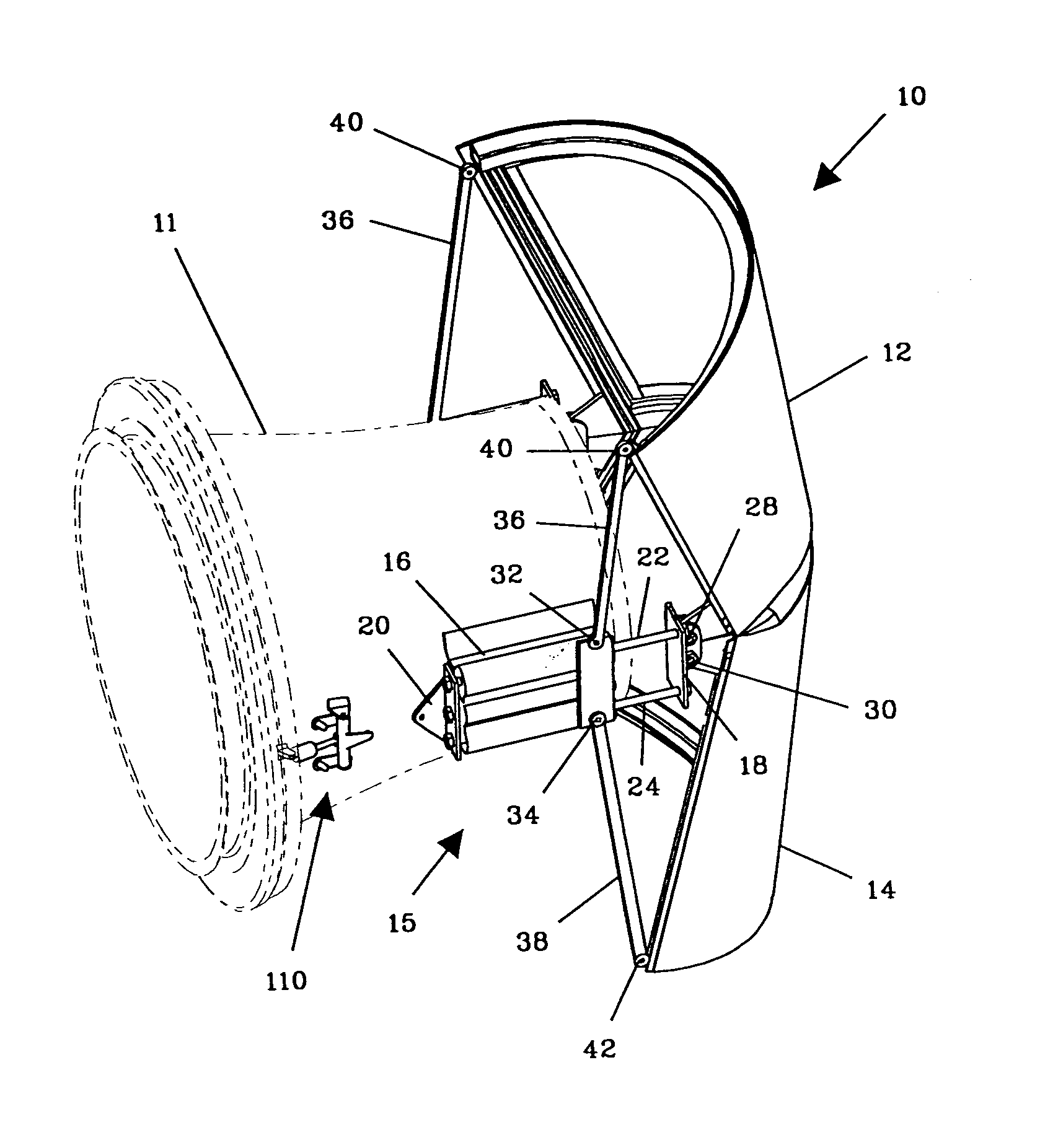
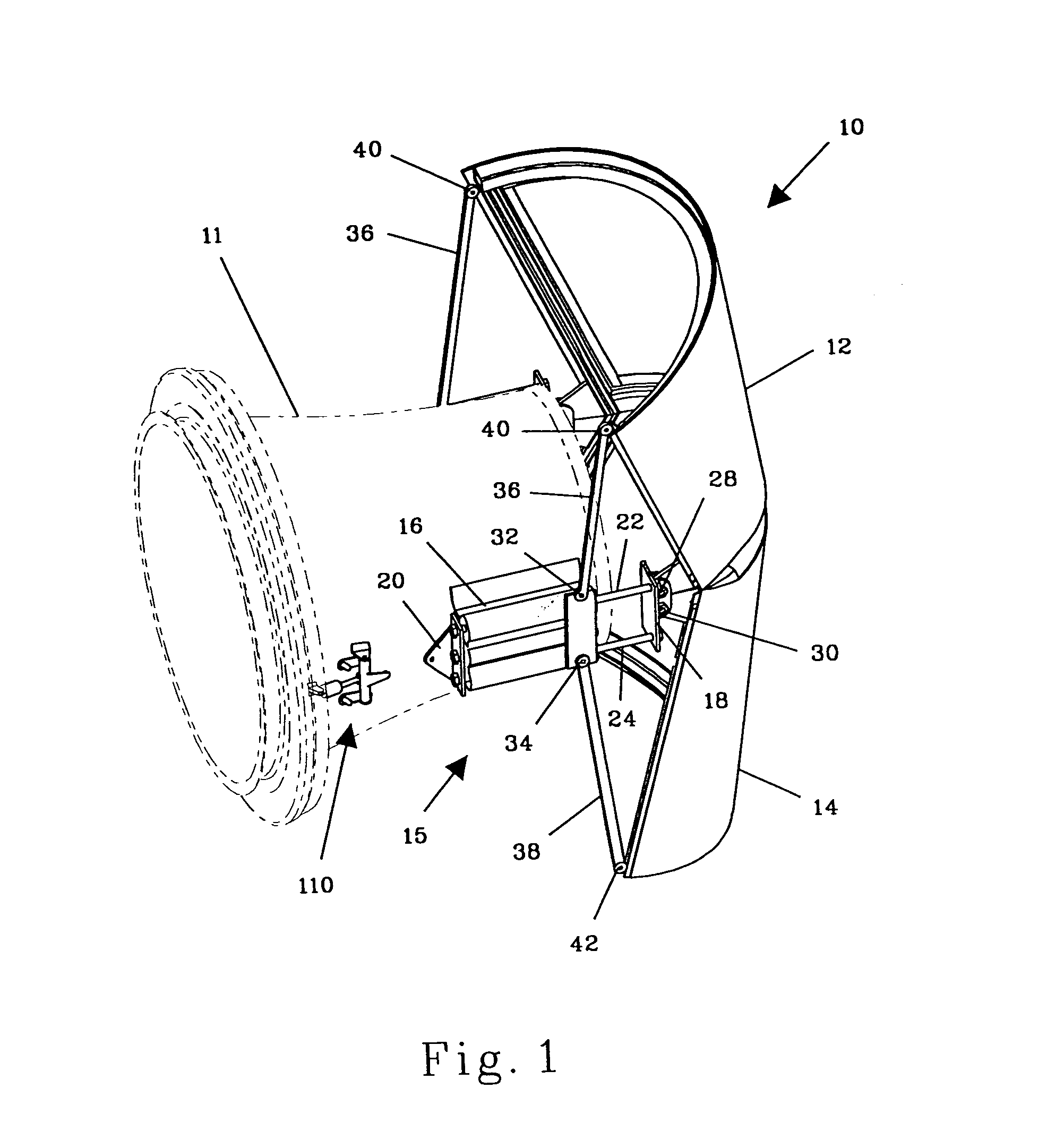
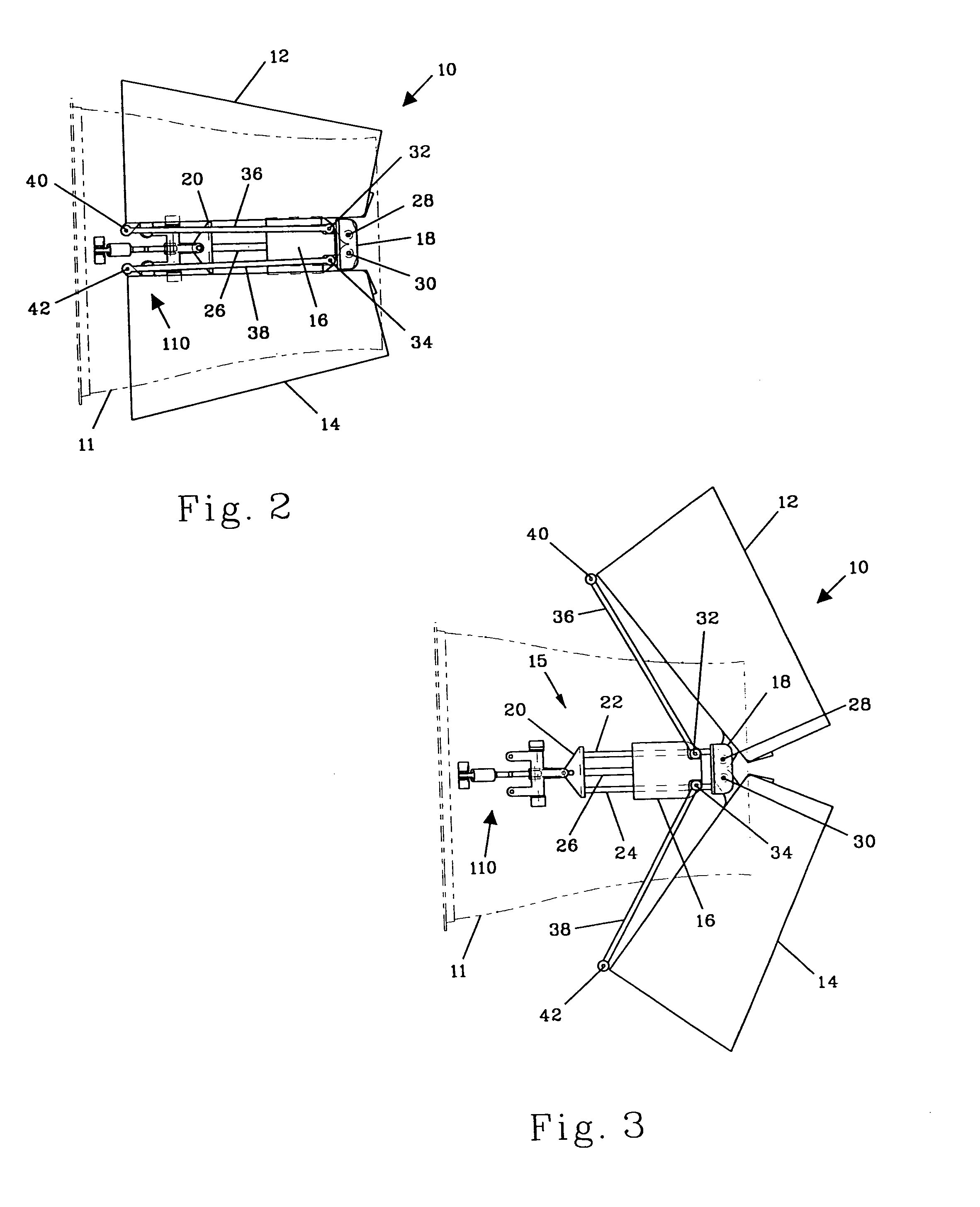
[0033]Referring to FIGS. 1–4, a thrust reverser 10 in accordance with the present invention preferably comprises a pair of doors 12 and 14 mounted to the exit nozzle 11 of a jet engine with an actuator assembly 15 on each side of nozzle 11. Each actuator assembly 15 preferably comprises a combined actuator and guide body 16, which is fixedly attached to nozzle 11. Each actuator / guide body 16 preferably comprises a conventional hydraulic or pneumatic actuator, although the actuator may be powered by other means such as electricity. On each side of door 12, a link rod 36 is pinned to the forward portion of door 12 at pin connection 40, and link rod 36 is pinned to actuator / guide body 16 at pin connection 32. Likewise, on each side of door 14, a link rod 38 is pinned to the forward portion of door 14 at pin connection 42, and link rod 38 is pinned to actuator / guide body 16 at pin connection 34. Although pin connections 32 and 34 are indicated as being fixed to actuator / guide body 16, p...


PUM


Abstract

A target type thrust reverser is provided for reversing the thrust of jet engines, particularly on aircraft. The thrust reverser preferably has a plurality of doors that occupy a stowed position about the nozzle of the jet engine until deployed. In the stowed position, the doors are out of the exhaust stream of the jet engine. The doors are mounted to pivot joints on the rear portions of the doors. To deploy the thrust reverser, actuators connected to the pivot joints cause the pivot joints to translate linearly aft, and link rods attached to the forward portions of the doors cause the doors to pivot about the sliding pivot joints. In this manner, the distance between the doors and the engine exhaust nozzle is minimized during deployment, which enables significant weight savings due to reduced loads and fewer parts. A novel lock is also provided for simultaneously locking the thrust reverser doors and the actuators.

Description

CROSS-REFERENCE TO RELATED APPLICATIONS[0001]This application is a divisional of U.S. patent application No. 09 / 909,561, filed Jul. 20, 2001 now U.S. Pat. No. 6,845,945, the full disclosure of which is incorporated herein by reference.BACKGROUND OF THE INVENTION[0002]1. Field of the Invention[0003]This invention relates generally to thrust reversers for jet engines, and more particularly to a target type thrust reverser in which the doors are mounted to sliding pivot joints.[0004]2. Description of the Related Art[0005]In the field of jet engines, and particularly in the field of jet aircraft engines, it frequently becomes advantageous to reverse the thrust of the engine in order to supply a braking force to the structure to which the engine is attached. On jet aircraft, thrust reversers are typically used to shorten the distance that the aircraft travels on the runway after landing and to enhance safety when braking the aircraft on a damp or icy runway. Various types of thrust rever...

Claims


Application Information

Patent Timeline
Patent Type & Authority Patents(United States)
IPC IPC(8): B64C25/68B64D33/04F02K1/60F02K1/76
CPCB64D33/04F02K1/76F02K1/60
Inventor SMITH, CRAIG M.
Owner AIRCRAFT INTEGRATION RESOURCES
Why Eureka
Try Eureka