
Monolithic ink-jet printhead and method for manufacturing the same

a monolithic inkjet and printhead technology, applied in printing and other directions, can solve the problems of high heat load on the printhead, complicated manufacturing process, and printhead operation stably, and achieve the effect of increasing the directionality of ink ejection and ejection performan

Active Publication Date: 2006-09-12
HEWLETT PACKARD DEV CO LP
View PDF9 Cites 45 Cited by
  • Summary
  • Abstract
  • Description
  • Claims
  • Application Information

AI Technical Summary

Benefits of technology

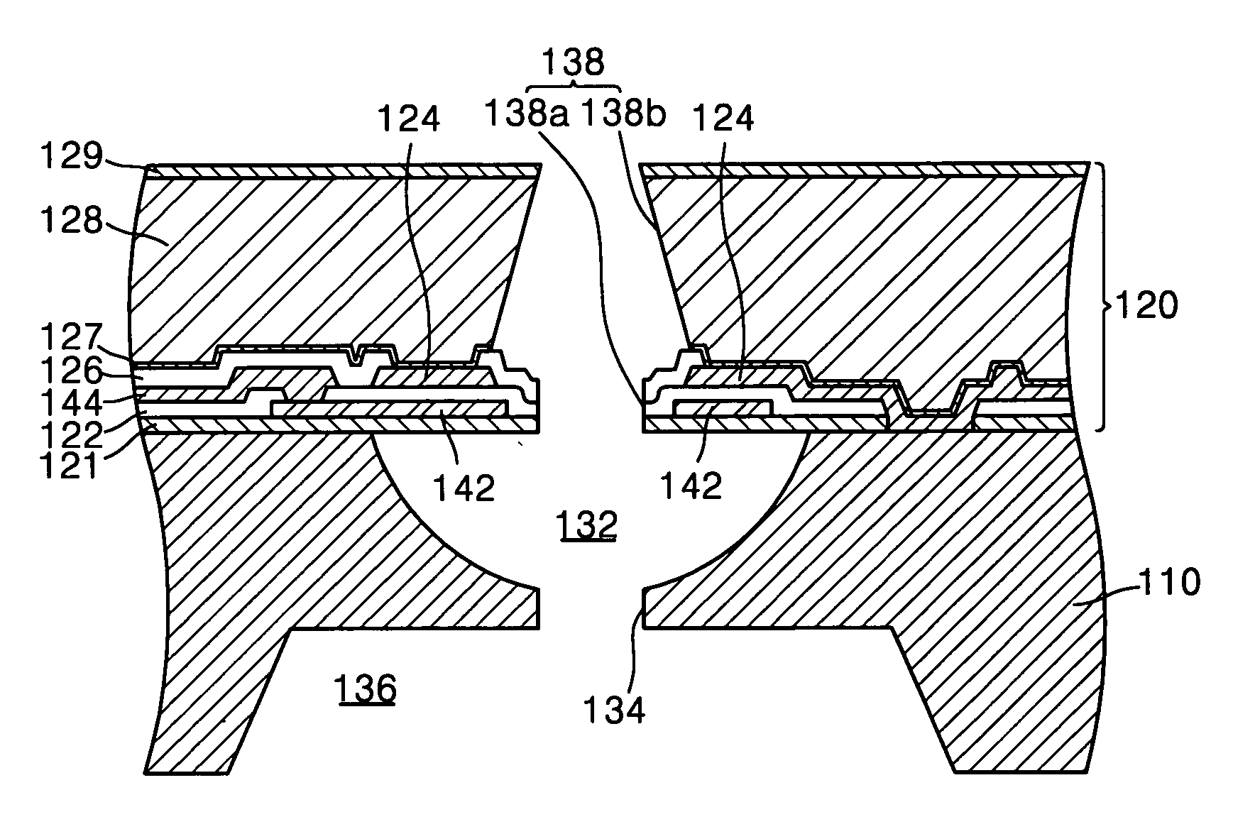
[0018]It is a feature of an embodiment of the present invention to provide a monolithic ink-jet printhead having a nozzle plate, which includes a thick metal layer, that is formed integrally with a substrate and a hydrophobic coating layer that is formed exclusively on an outer surface of the metal layer of the nozzle plate, thereby increasing the directionality of ink ejection and the ejection performance.

Problems solved by technology

Fourth, heat load exerted on the printhead due to heat generated by the heater must be small, and the printhead must operate stably under a high operating frequency.
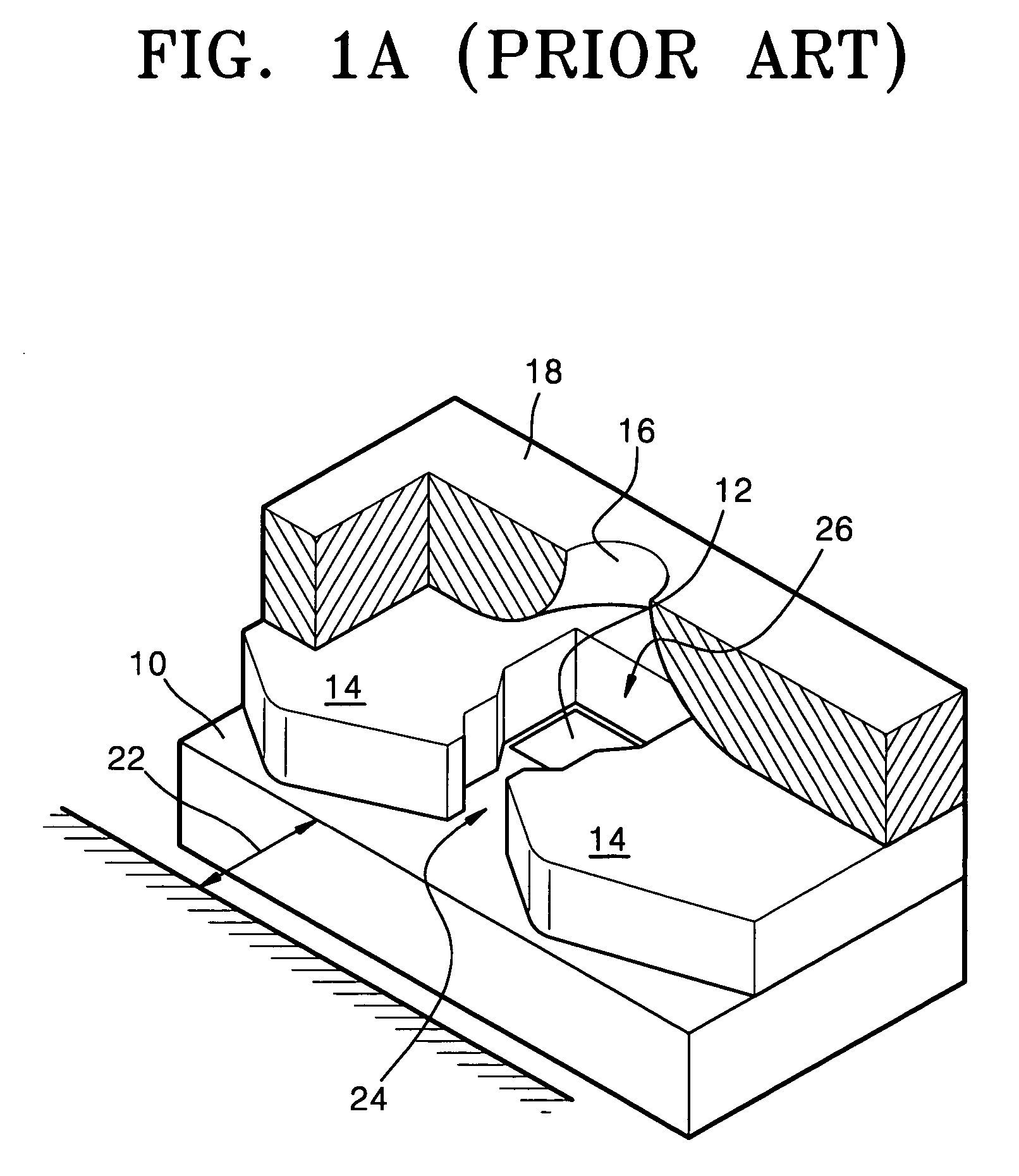
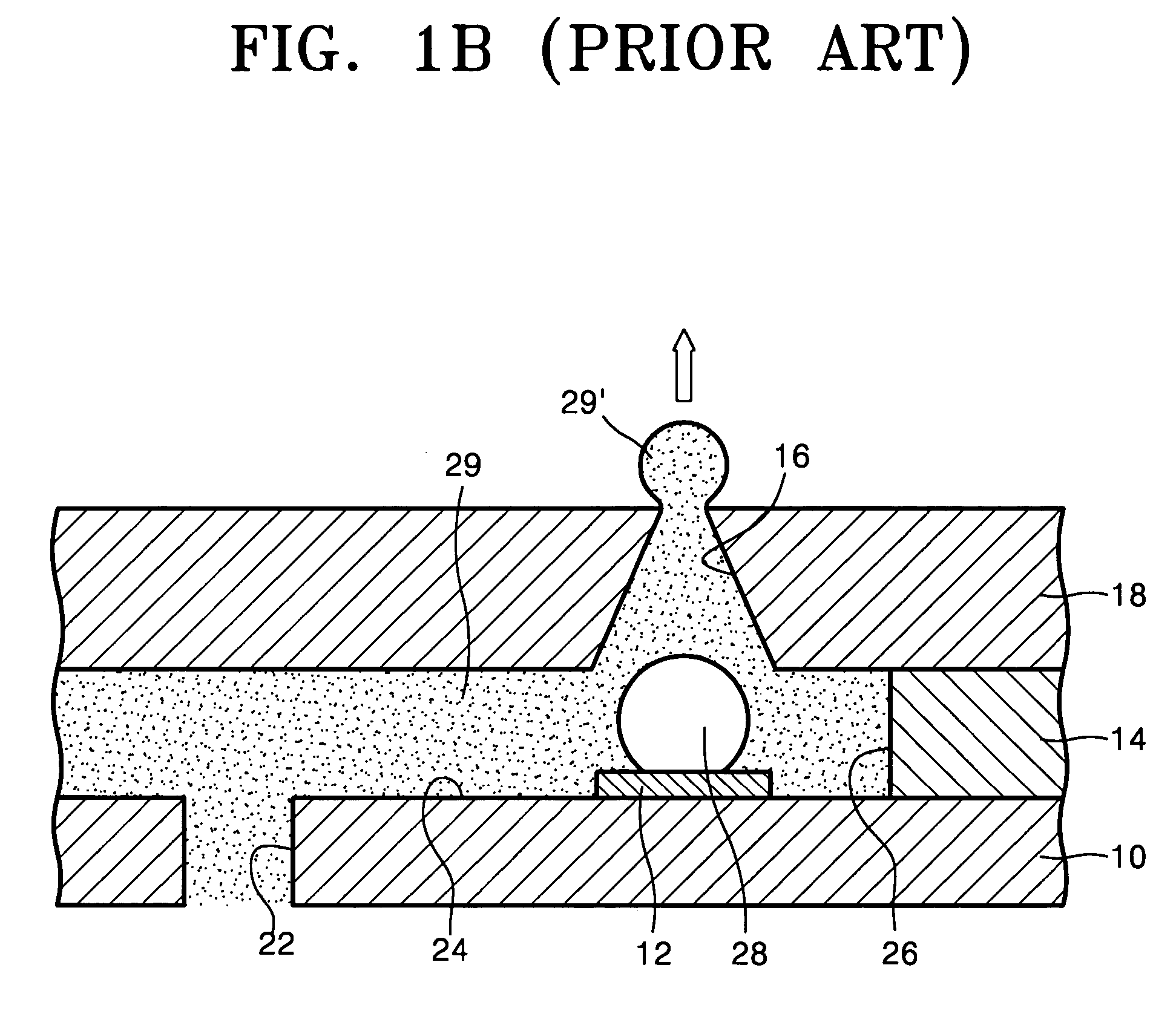
The manufacturing process is complicated and misalignment may occur during the bonding of the nozzle plate-18 and the substrate 10.
This restriction makes it difficult to implement a high printing speed, high-resolution ink-jet printhead.
In particular, the surface property of the nozzle plate greatly affects the characteristic of the ink ejection.
Thus, a considerable amount of time is required for the heater 45, the ink 48 within the ink chamber 32, and a nozzle guide 44, all of which are heated during the ejection of the ink 48, to sufficiently cool and return to an initial state, thereby making it difficult to increase the operating frequency to a sufficient level.
However, if the nozzle guide 44 is too long, this not only makes it difficult to form the ink chamber 32 by etching the substrate 30 but also restricts expansion of the bubbles 49.

Method used


Image

  • Monolithic ink-jet printhead and method for manufacturing the same
  • Monolithic ink-jet printhead and method for manufacturing the same
  • Monolithic ink-jet printhead and method for manufacturing the same

Examples


Embodiment Construction

[0044]Korean Patent Application No. 2002-77000, filed on Dec. 5, 2002, end entitled: “Monolithic Ink-Jet Printhead and Method for Manufacturing the Same,” is incorporated by reference herein in its entirety.

[0045]The present invention will now be described more fully hereinafter with reference to the accompanying drawings, in which a preferred embodiment of the invention is shown. The invention may, however, be embodied in different forms and should not be construed as limited to the embodiments set forth herein. Rather, these embodiments are provided so that this disclosure will be thorough and complete, and will fully convey the scope of the invention to those skilled in the art. In the drawings, the thickness of layers and regions and the sizes of components may be exaggerated for clarity. It will also be understood that when a layer is referred to as being “on” another layer or substrate, it can be directly on the other layer or substrate, or intervening layers may also be prese...


PUM


Abstract

A monolithic ink-jet printhead includes a substrate which has an ink chamber to be supplied with ink, a manifold for supplying ink to the ink chamber, and an ink channel for providing communication between the ink chamber and the manifold, a nozzle plate including a plurality of passivation layers sequentially stacked on the substrate, a metal layer formed on the passivation layers, and a nozzle, through which ink is ejected from the ink chamber, that penetrates the nozzle plate, a heater provided between adjacent passivation layers, the heater being located above the ink chamber for heating ink within the ink chamber, a conductor provided between adjacent passivation layers, the conductor being electrically connected to the heater for applying a current to the heater, and a hydrophobic coating layer formed exclusively on an outer surface of the metal layer.

Description

BACKGROUND OF THE INVENTION[0001]1. Field of the Invention[0002]The present invention relates to an ink-jet printhead. More particularly, the present invention relates to a thermally driven, monolithic, ink-jet printhead having a nozzle plate that is formed integrally with a substrate and a hydrophobic coating layer formed on a surface of the nozzle plate, and a method for manufacturing the same.[0003]2. Description of the Related Art[0004]In general, ink-jet printheads are devices for printing a predetermined image, color or black, by ejecting a small volume ink droplet of a printing ink at a desired position on a recording sheet. Ink-jet printheads are largely classified into two types depending on the ink droplet ejection mechanisms: a thermally driven ink-jet printhead, in which a heat source is employed to form and expand a bubble in ink thereby causing an ink droplet to be ejected, and a piezoelectrically driven ink-jet printhead, in which a piezoelectric crystal bends to exer...

Claims


Application Information

Patent Timeline
Patent Type & Authority Patents(United States)
IPC IPC(8): B41J2/05B41J2/135B41J2/14B41J2/16
CPCB41J2/14129B41J2/14137B41J2/1601B41J2/1606B41J2/1625B41J2/1628B41J2/1631B41J2/1642B41J2/1643B41J2/1646B41J2/1626B41J2002/1437B41J2/135
Inventor SONG, HOONOH, YONG-SOOSHIN, JONG-WOOLEE, CHANG-SEUNGLIM, HYUNG-TAEK
Owner HEWLETT PACKARD DEV CO LP
Learn More