Reshapeable tip for a cryoprobe

a cryoprobe and tip technology, applied in the field of surgical cryoprobes, can solve the problems of increasing the risk of patients, affecting the success of procedures, and time-consuming multiple contact, and achieve the effect of convenient bending or curved

Inactive Publication Date: 2006-09-12
CRYOCOR
View PDF26 Cites 20 Cited by
  • Summary
  • Abstract
  • Description
  • Claims
  • Application Information

AI Technical Summary

Benefits of technology

[0010]Also for the present invention, the device includes a shapeable element that is attached to the distal end of the shaft and extends through the opening of the enclosure and into the cryochamber. For the present invention, the shapeable element is sized and made of a suitable material and size to allow the element to be shaped (i.e., plastically deformed) with selected curves, bends and combinations thereof. In a typical embodiment, the shapeable element is made of a relatively soft metal such as annealed or slightly worked copper and is initially shaped as a straight rod. In one embodiment, the shapeable element is designed to be somewhat easily bent or curved by the operating physician using normal hand strength.

Problems solved by technology

However, in most procedures, the exposed surface of the target tissue is contoured and this contour often precludes the establishment of large or extended contact areas when using a conventional cylindrical probe.
This requirement of multiple contacts is time consuming and can present an increased risk to the patient due to the lengthy duration of the procedure.
In addition, the use of multiple contacts can often result in the non-uniform ablation of tissue that can undermine the success of the procedure.
Another case in which a standard cylindrical probe may be inadequate is when the target tissue cannot be adequately exposed for contact with the conventional cylindrical probe.
In still other cases, adequate exposure for contact with a conventional cylindrical probe may be possible, but an unreasonable amount of time may be required to effect such an exposure.
In addition to having an adequate contact area between the probe and tissue, proper heat transfer requires that an unimpeded flow of refrigerant pass through the probe tip.

Method used


Image

  • Reshapeable tip for a cryoprobe
  • Reshapeable tip for a cryoprobe

Examples


Embodiment Construction

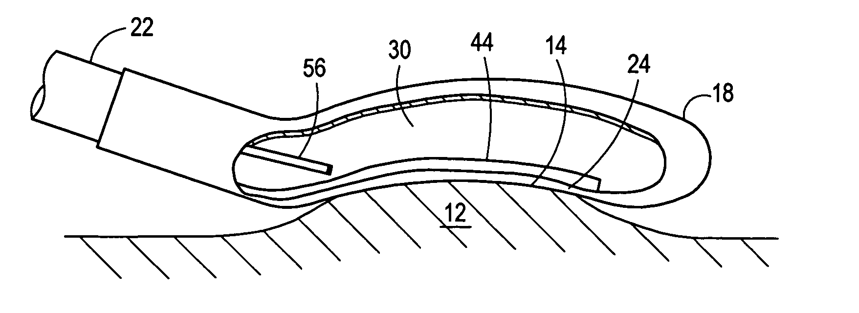
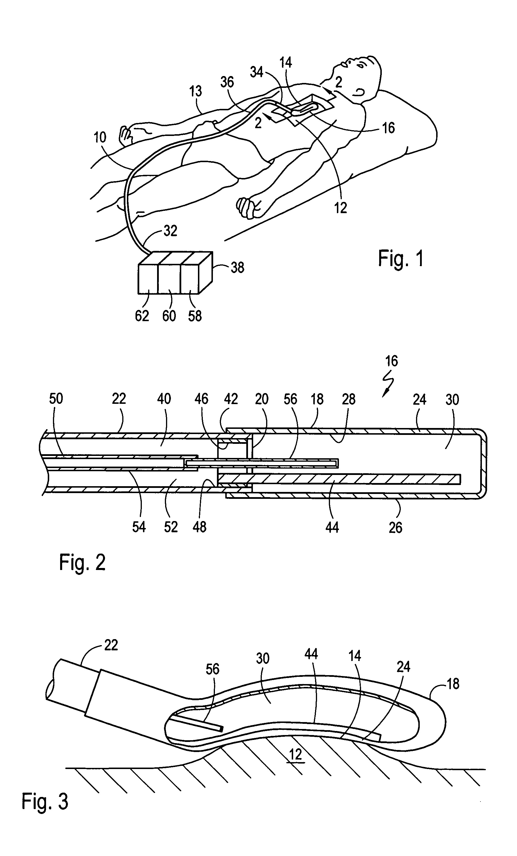
[0018]Referring initially to FIG. 1, a device 10 for cryoablating exposed tissue 12 of a patient 13 is shown. In functional overview, the device 10 is particularly suitable for cryoablating exposed tissue 12 having a contoured surface 14 without requiring multiple contacts between the device 10 and the exposed tissue 12. To achieve this functionality, the distal tip 16 of the device 10 is reshapeable to conform with the contoured surface 14.

[0019]As best seen in FIG. 2, the distal tip 16 includes a flexible enclosure 18 that is attached to the distal end 20 of a tube-shaped shaft 22. As further shown in FIG. 2, the flexible enclosure 18 is formed with a cylindrical shaped wall 24 having an outer surface 26 for contacting target tissue and an inner surface 28, opposed to outer surface 26, which establishes and surrounds a cryochamber 30. For the device 10, the wall 24 of the enclosure 18 is typically made of a flexible, thermally conductive material that will allow heat to pass throu...


PUM


Abstract

A device for cryoablating exposed tissue having a contoured contact surface includes a tube-shaped shaft and a flexible, thermally conductive enclosure that is attached to the distal end of the tube-shaped shaft. The enclosure is formed with a wall having an outer surface for contacting the target tissue and an inner surface which establishes and surrounds a cryochamber. A shapeable element is attached to the distal end of the shaft and extends into the cryochamber. The element can be permanently deformed into a pre-selected shape to cause a portion of the enclosure wall to conform to the contour of the target tissue. A high-pressure tube in the shaft passes a refrigerant through the shaft for expansion into the cryochamber. This expansion cools the wall of the enclosure, which in turn, extracts heat from the target tissue resulting in the cryoablation of the target tissue.

Description

FIELD OF THE INVENTION[0001]The present invention pertains generally to surgical equipment. More particularly, the present invention pertains to surgical cryoprobes for cryoablating exposed tissue. The present invention is particularly, but not exclusively, useful for cryoablating exposed tissue having a contoured surface.BACKGROUND OF THE INVENTION[0002]Cryosurgical probes have been selectively used in the treatment of a variety of diseases. Functionally, cryosurgical probes have the capability of reducing the temperature of a targeted body tissue to thereby destroy, remove and / or inactivate the tissue. Because of this ability, the use of cryothermal treatment has been prescribed in the treatment of various cancers, including breast cancer and prostate cancer, as well as to remove various tumors, cysts and in the treatment of cataracts. More recently, the use of cryothermal treatment has been shown to be effective in destroying specific conductive tissues of the heart. This techniq...

Claims


Application Information

Patent Timeline
Patent Type & Authority Patents(United States)
IPC IPC(8): A61B18/18A61B18/02
CPCA61B18/02A61B2018/0262
Inventor RYBA, ERIC
Owner CRYOCOR
Why Eureka
Try Eureka