Magnetic disk and method of manufacturing same

a magnetic disk and manufacturing method technology, applied in the field of magnetic disk manufacturing, can solve the problems of magnetic disk damage, head crash, frequent flying stick impairment,

Inactive Publication Date: 2006-09-12
WD MEDIA SINGAPORE PTE
View PDF12 Cites 74 Cited by
  • Summary
  • Abstract
  • Description
  • Claims
  • Application Information

AI Technical Summary

Problems solved by technology

However, when the magnetic head is moved rapidly while flying over the surface of the magnetic disk at an extremely low level, there are problems in that “fly-sticking” impairment and head corrosion impairment frequently occur.
In some cases, the magnetic disk contacts the magnetic head during flying, causing the head to crash and damaging the magnetic disk.
“Corrosion” impairment refers to impairment in the form of the corrosion of elements of the magnetic head that creates problems during recording and reproduction, and in some causes, renders recording and reproduction impossible.
The corroded elements sometimes expand, damaging the surface of the magnetic disk during flying.
When the magnetic disk is rotated at such high speeds, a phenomenon occurs in which the centrifugal force accompanying movement causes the lubricating layer to migrate, resulting in nonuniformity of the thickness of the lubricating layer within the magnetic disk surface.
When the thickness of the lubricating layer is increased on the outer circumference portion of the disk, fly-sticking impairment and head crashing impairment tend to occur when the magnetic head enters from the outer circumferential portion of the disk during an LUL operation.
When the thickness of the lubricating layer is reduced on the inner circumferential portion, the reduction in lubricating performance tends to cause head crashing.
When they are employed in LUL-system magnetic disks, the frequency of the above-described impairments is high, and it is already difficult to satisfy the reliability that has recently come to be required of magnetic disks.
Thus, they have become factors impeding the development of high-capacity, high S / N ratio, rapid-response LUL-system magnetic disks.

Method used


Image

  • Magnetic disk and method of manufacturing same
  • Magnetic disk and method of manufacturing same

Examples


embodiment 1

(Embodiment 1)

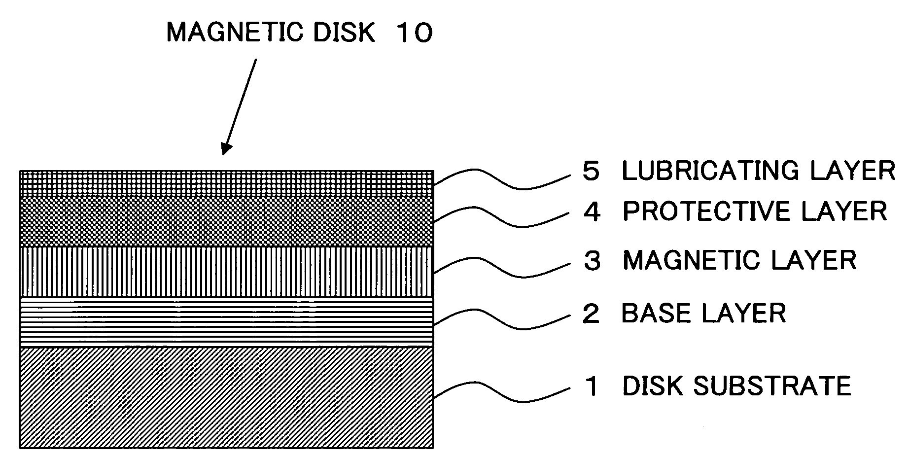
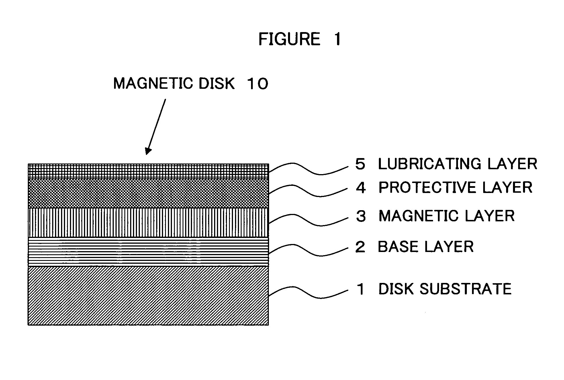
[0065]FIG. 1 shows a magnetic disk 10 in an implementation mode of the present invention.

[0066]In magnetic disk 10, on a disk substrate 1 are sequentially formed a base layer 2, magnetic layer 3, protective layer 4, and lubricating layer 5. Lubricating layer 5 is formed out of the lubricant (referred to as lubricant c) of the present invention. This will be described more specifically below.

(Preparation of the Lubricant)

[0067]The method of preparing the lubricant will be described.

[0068]First, Fomblin Ztetraol (product name) made by Solvay Solexis (referred to as lubricant alpha below) was selected and procured as the lubricant containing the above perfluorotetraol compound and perfluorodiol compound. A pressure column was mounted on a supercritical fluid application device configured of a supercritical fluid delivery device, temperature regulating device, pressure regulating device, FTIR, and ultraviolet-visible spectrum detector. Carbon dioxide was employed as the mo...

embodiments 2 and 3

(Embodiments 2 and 3)

[0088]In Embodiment 2, the blending proportion of compositions A and B was varied to achieve a weight ratio of 1:2 of lubricant a to lubricant b.

[0089]In Embodiment 3, the mixing ratio of compositions A and B was varied to achieve a blending proportion by weight of 2:1 of lubricant a to lubricant b. These exceptions aside, these embodiments were identical to Embodiment 1.

[0090]When LUL durability testing was conducted in the same manner as in Embodiment 1, both Embodiments 2 and 3 achieved the same good results as Embodiment 1.

[0091]A detailed analysis of the lubricating layers of the magnetic disks of each of Embodiments 1 through 3 by TOF-SIMS revealed that the magnetic disks of all of the embodiments contained —COOH atomic groups and —CF2COOH atomic groups in the lubricating layer. These atomic groups were not contained in either the above perfluorotetraol compound or the above perfluorodiol compound; nor were they contained in lubricant alpha, lubricant beta...


PUM

PropertyMeasurementUnit
flying heightaaaaaaaaaa
temperatureaaaaaaaaaa
pressureaaaaaaaaaa

Abstract

Disclosed is a method of manufacturing magnetic disks, comprising a magnetic layer, a protective layer, and a lubricating layer on a substrate. In the process, a lubricant alpha comprising a compound denoted by chemical formulaHO—CH2—CH(OH)—CH2—O—CH2—CF2(—O—C2F4)p-(O—CF2)q-O—CF2—CH2—O—CH2—CH(OH)—CH2—OHwherein p and q are natural number,and a compound denoted by chemical formulaHO—CH2—CF2(—O—C2F4)m-(O—CF2)n-O—CF2—CH2—OHwherein m and n are natural number,is fractionated by molecular weight to prepare a lubricant a having a weight average molecular weight (Mw) of from 3,000 to 7,000 and a molecular weight dispersion of less than or equal to 1.2;a lubricant beta comprising a compound denoted by the chemical formulaHO—CH2—CF2(—O—C2F4)m-(O—CF2)n-O—CF2—CH2—OHwherein m and n are natural number,is fractionated by molecular weight to prepare a lubricant b having a weight average molecular weight (Mw) of from 2,000 to 5,000 and a molecular weight dispersion of less than or equal to 1.2;a lubricant c comprising a mixture of lubricants a and b is prepared; anda film of lubricant c is formed on a protective layer provided on a substrate to form a lubricating layer. A magnetic disk comprising a magnetic layer, a protective layer, and a lubricating layer on a substrate, in which the lubricating layer has been formed on the protective layer is also enclosed.

Description

TECHNICAL FIELD[0001]The present invention relates to a method of manufacturing magnetic disks to be loaded into magnetic disk devices such as hard disk drives, as well as to magnetic disks.BACKGROUND TECHNOLOGY[0002]In magnetic disk devices such as hard disk drives (HDDs), a contact start and stop (CSS) system is employed in which a magnetic head is brought into contact with a contact slide area (CSS area) located in the inner-circumferential area of the magnetic disk surface when stopped, and the magnetic head flies upward while sliding in contact with the disk surface in the CSS area and then recording or reproduction is conducted in a disk area surface for recording and reproduction that is located to the outside of the CSS area when activated. When an operation has been completed, the magnetic head is withdrawn from the recording and reproduction area into the CSS area, after which the magnetic head descends while sliding in contact with the disk surface in the CSS area and com...

Claims


Application Information

Patent Timeline
Patent Type & Authority Patents(United States)
IPC IPC(8): G11B5/66G11B5/70C10M105/54C10M107/38C10M171/04C10N40/18G11B5/64G11B5/72G11B5/725G11B5/84
CPCC10M107/38C10M171/04G11B5/8408G11B5/725C10M2211/0425C10M2213/043C10N2220/021C10N2240/204C10N2250/121C10N2270/00C10N2020/04C10N2040/18C10N2050/02C10N2070/00G11B5/7257
Inventor SHIMOKAWA, KOICHIISHIYAMA, MASAFUMI
Owner WD MEDIA SINGAPORE PTE
Why Eureka
Try Eureka