Plant, generator and propeller element for generating energy from watercurrents

a technology of propeller elements and water currents, applied in the direction of electrical apparatus, climate sustainability, artificial islands, etc., can solve the problems of further energy loss, complex solution, electrical and mechanical power loss,

Inactive Publication Date: 2006-09-12
HYDRA TIDAL ENERGY TECH
View PDF36 Cites 99 Cited by
  • Summary
  • Abstract
  • Description
  • Claims
  • Application Information

AI Technical Summary

Problems solved by technology

The previously known contra-rotating propellers connected to the same generator require complex gearwheel drive and transmissions, which results in further energy loss.
A contra-rotating propeller connected to the rotor and the stator respectively is much simpler from a mechanical point of view, but in the solutions known hitherto the field coils require slip rings which may render the solution more complex, in addition to there being an electrical and mechanical power loss.
The consequence is a high torque and it is very difficult to dimension a standard gear solution.
This results in the generator housing having a very large diameter, which is a disadvantage.
The disadvantage of this generator is that much energy is lost in the many transmissions that are used to contra-rotate the stator.
Furthermore, this generator is bulky, and will probably be expensive both to manufacture and to maintain.
The drawback with this generator is that it includes an outer member which does not rotate, and which is equipped with a conventional stator winding.

Method used


Image

  • Plant, generator and propeller element for generating energy from watercurrents
  • Plant, generator and propeller element for generating energy from watercurrents
  • Plant, generator and propeller element for generating energy from watercurrents

Examples


Embodiment Construction

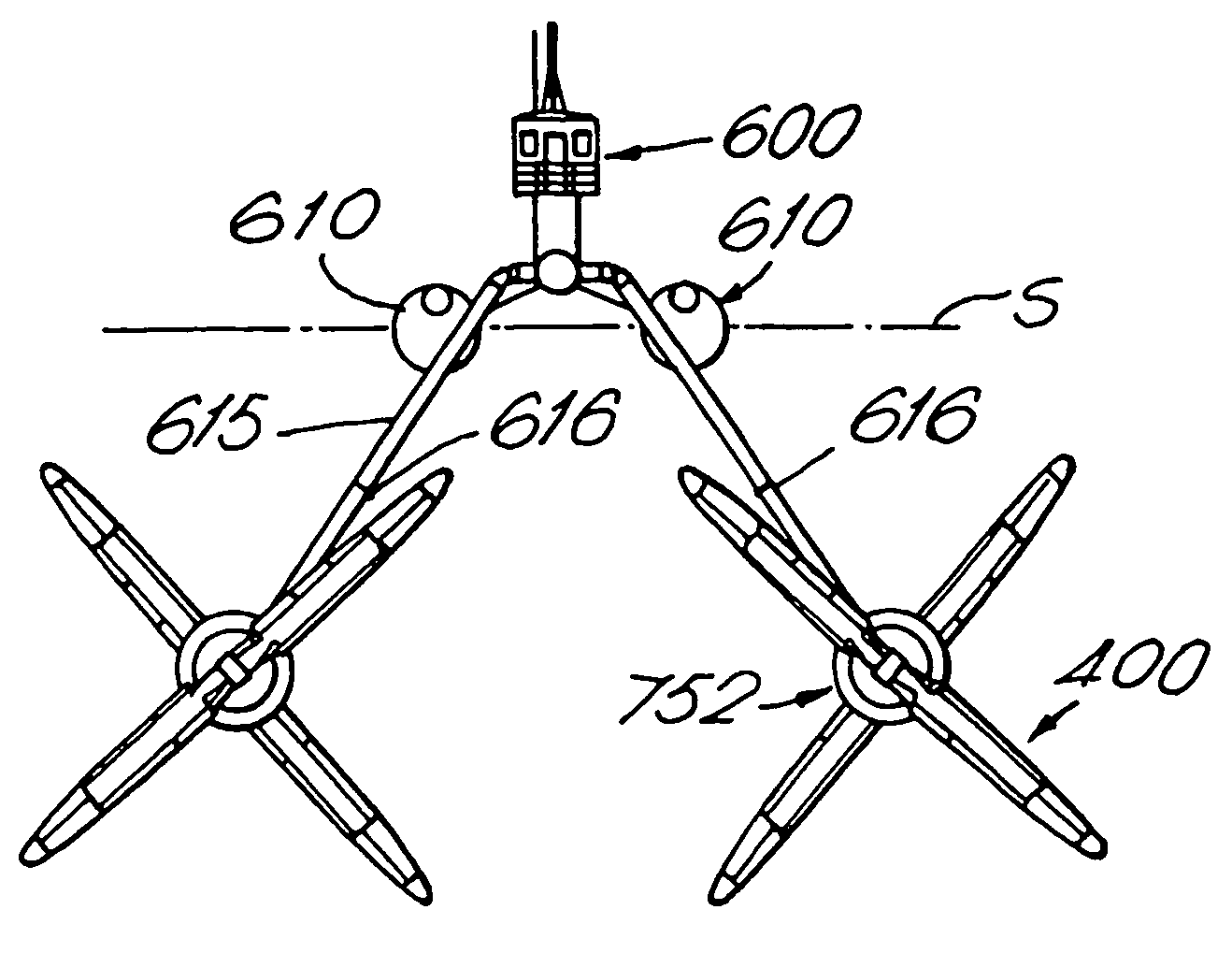
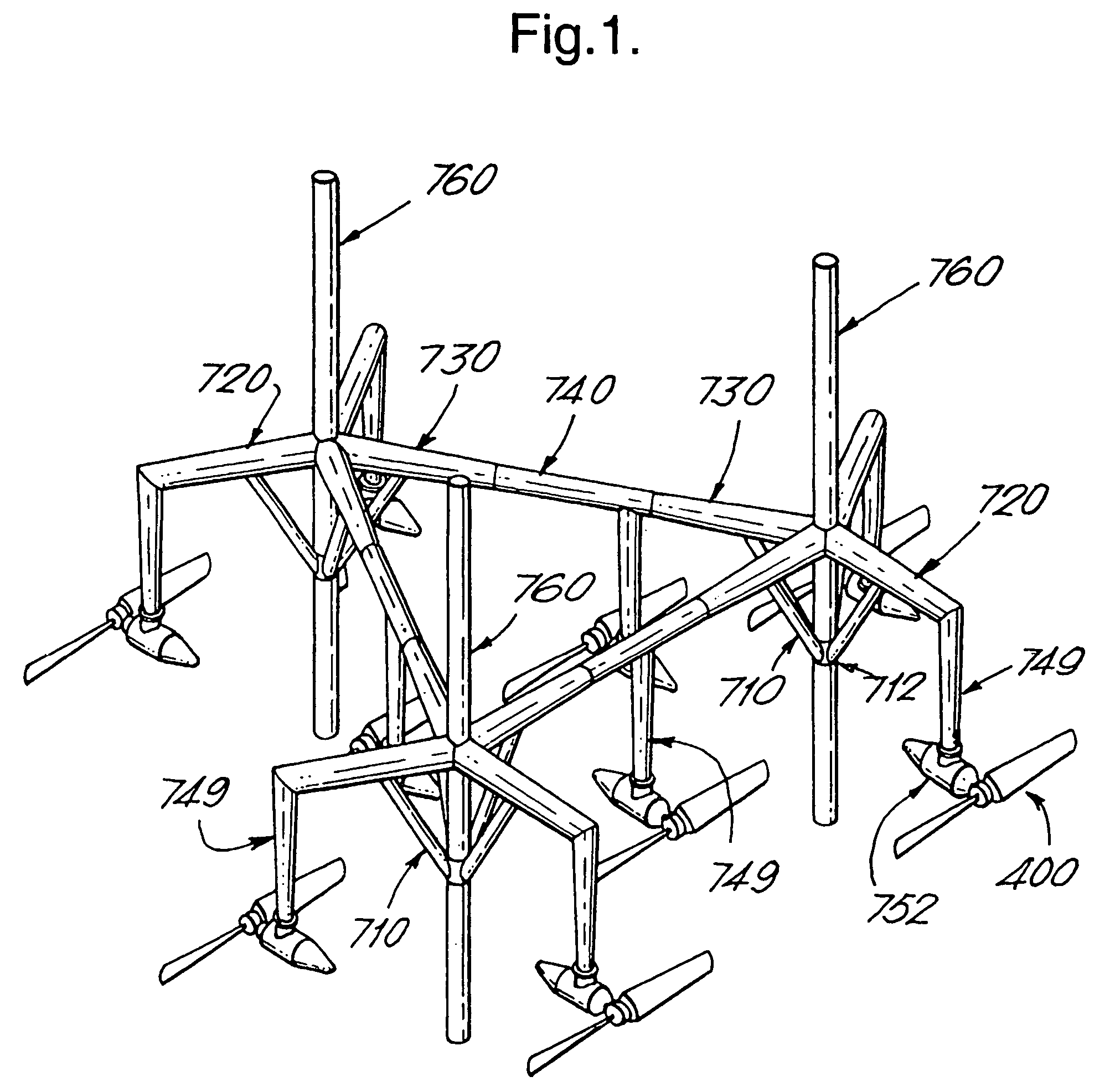
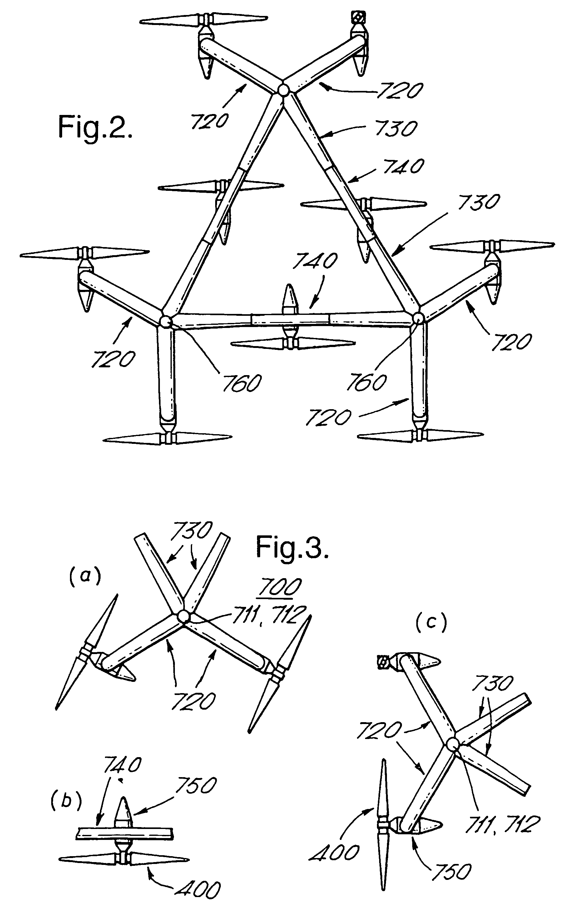
[0053]In one embodiment, the plant according to the invention comprises a structure capable of resting on a bottom B below the surface S of a body of water. The structure supports a plurality of replaceable generator units 750 which are driven by the water currents. The plant structure is built up of a plurality of nodal elements 700 having a respective nodal centre, and substantially horizontal supporting members 720 and connecting members 730 projecting therefrom. Upper and lower bushings 711, 712 for a height adjustable leg 760 extending towards the bottom B pass through each nodal centre.

[0054]The nodal elements 700 are interconnected by means of intermediate connecting members 740 between the connecting members 730.

[0055]The generator units 750 are secured to substantially vertical supporting members 749, each of which may be secured to the horizontal supporting members 720 or the intermediate connecting members 740.

[0056]For production and hydrodynamic reasons, the arms, the s...


PUM


Abstract

A plant, generator and rotating member for the production of power from currents in a body of water, comprising a fixedly mounted of floating structure, and a plurality of replaceable generator units (750) supported by the structure and which are driven by the water currents. The structure comprises arms (615, 720, 730). The rotating member (400) comprises a plurality of member sections (410) rotatably mounted on a shaft (405) between an end piece (407) and a tip (406). The generator comprises a contra-rotating rotor (550) and stator (800) connected to respective shafts (500, 820) and bearings, where the stator frame (800) is axially supported (810) on the first shaft (500) and the first shaft (500) at one end thereof is axially supported (810) on the stator frame. The generator according to the invention can be used for the production of electric power, and as an electromotor for the production of mechanical rotational energy.

Description

TECHNICAL FIELD[0001]The invention relates to apparatus for extracting energy from water currents. More specifically, the invention relates to plants for the production of energy from currents in a body of water, comprising a structure capable of resting on a bottom below the body of water or of floating on the body of water and a plurality of replaceable generator units supported by the structure and which are driven by the water currents, and a rotating member for use as energy supplier in a generator unit located in a body of water a generator, more specifically a generator in which the stator and the rotor are rotatable relative to one another. The plant utilises currents below the surface of oceans, seas, rivers or other bodies of water. Such currents may, e.g., be caused by tidal variations and / or underwater topography (e.g., channels, riverbeds or other narrow passages under water).[0002]The generator according to the invention can produce electric power by utilising any sour...

Claims


Application Information

Patent Timeline
Patent Type & Authority Patents(United States)
IPC IPC(8): F03D9/00F02N11/04F03B13/12H02P9/04F02N11/00B63B35/44F03B11/00F03BF03B1/00F03B1/02F03B13/10F03B13/26F03B17/06H02K7/18H02K16/00H02P9/00
CPCB63B35/44F03B1/02F03B17/061H02K7/1823H02K16/00H02K16/005Y02E10/38E02B2017/0091F05B2210/16F05B2240/40F05B2240/97F05B2260/72Y02E10/223Y02E10/28B63B2035/4466Y02E10/20Y02E10/30F03B13/00Y02E10/72
Inventor HENRIKSEN, SVEIN DAG
Owner HYDRA TIDAL ENERGY TECH
Why Eureka
Try Eureka