Electric motor with the rotor connected to the member that is to be rotated

a technology of electric motors and rotors, applied in the direction of dynamo-electric machines, electrical apparatus, magnetic circuits, etc., can solve the problems of inability to mount directly on the axles of the drive wheels, the inability to manufacture, the inability to meet the requirements of space requirements, and the inability to meet the requirements of manufacturing costs, etc., to achieve the effect of reducing the cost of manufacturing, avoiding the effect of energy loss and imprecise transmission of driv

Inactive Publication Date: 2006-09-12
MANTOVANI
View PDF5 Cites 15 Cited by
  • Summary
  • Abstract
  • Description
  • Claims
  • Application Information

AI Technical Summary

Benefits of technology

[0006]The inventor of the present innovation has provided a solution to this problem by devising a motor which, while comprising the same essential parts (rotor, stator and frame) as electric motors of known type, can be mounted in a very much more advantageous way owing to the particular arrangement of its parts and their connections.

Problems solved by technology

However, this type of motor has serious limitations in its modes of use owing to the fact that it has to be mounted in the way hinted at above.
To take one example, in self-propulsion the fact that the shaft driven by the electric motor projects from one side only makes it impossible to mount it directly on the axles of the drive wheels.
This creates problems in terms of the manufacturing cost, space requirements, the inevitable energy losses and imprecision in the transmission of the drive.

Method used


Image

  • Electric motor with the rotor connected to the member that is to be rotated
  • Electric motor with the rotor connected to the member that is to be rotated
  • Electric motor with the rotor connected to the member that is to be rotated

Examples


Embodiment Construction

[0008]Two preferred embodiments suitable for self-propulsion applications will now be described in more detail by way of example, no limitation or restriction therefore being implied, for which purpose reference will also be made to the accompanying drawings, in which:

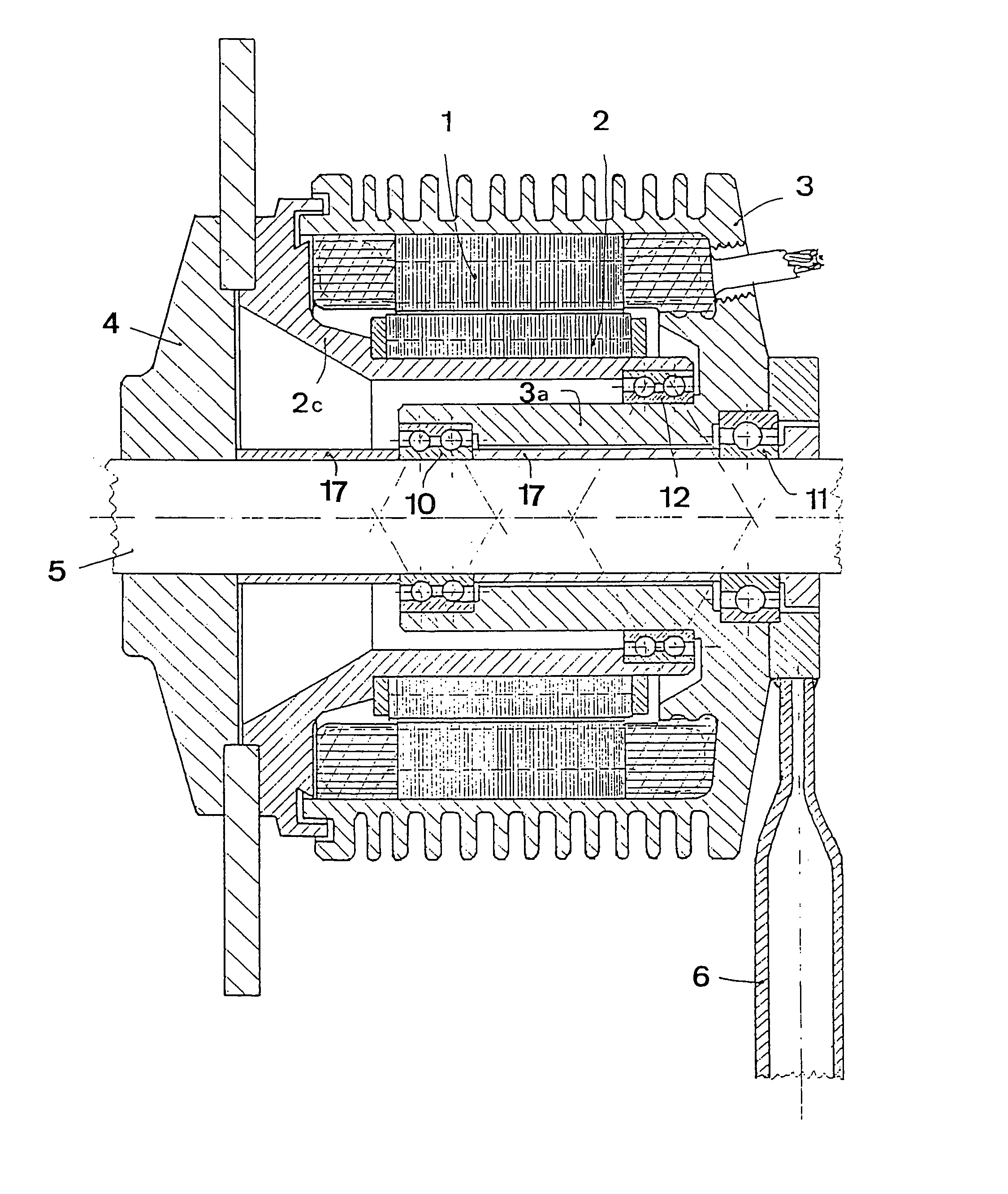
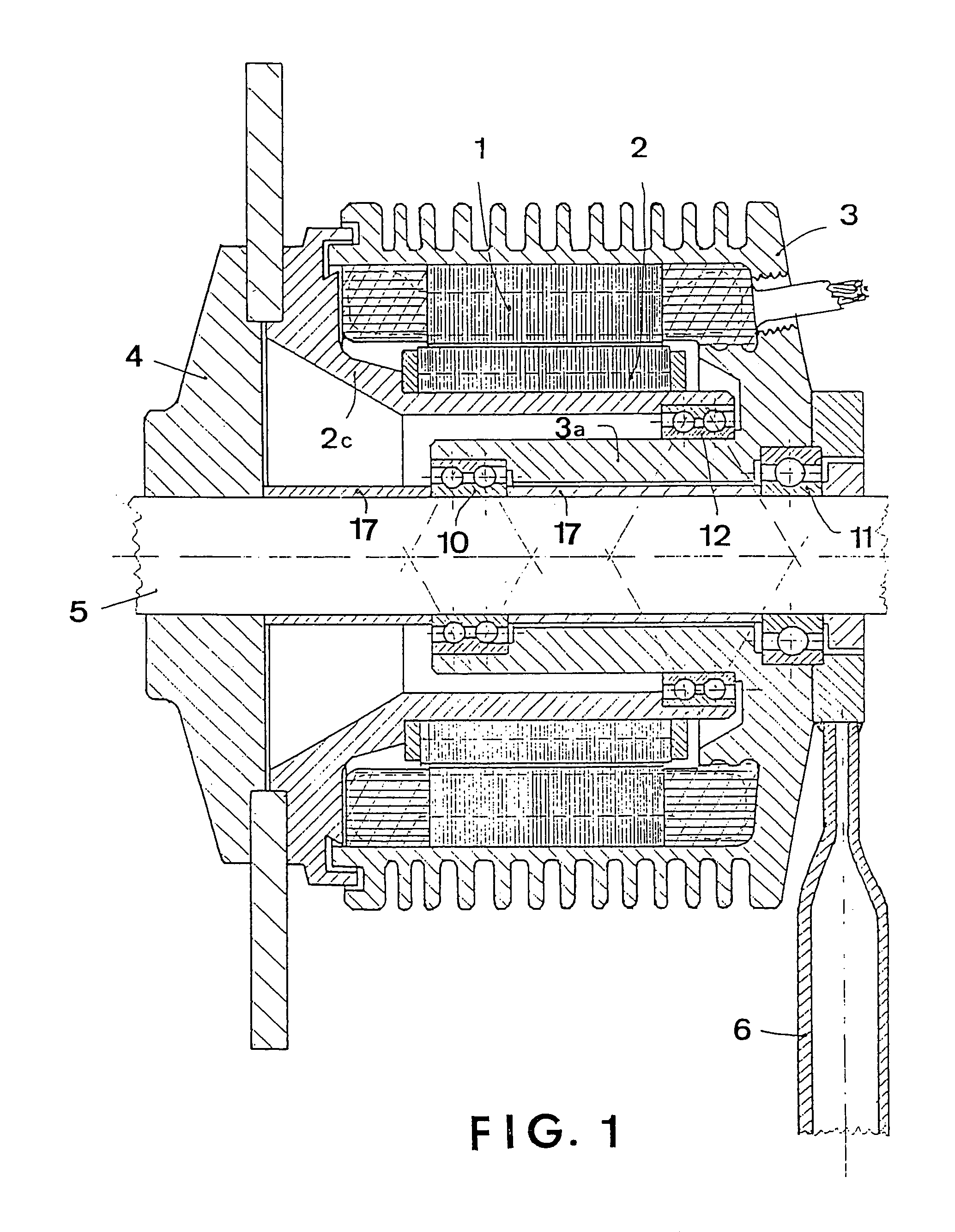
[0009]FIG. 1 is a view in longitudinal section of a preferred embodiment of the electric motor according to the invention connected to the hub of a wheel in the case in which a part of the rotor is directly fixed to the hub, while FIG. 2 shows the case in which this part is connected to the hub via intermediate speed-reducing gearing, and FIG. 3 shows a longitudinal section through a spindle powered by the electric motor of the invention.

[0010]Referring to FIG. 1, it can be seen that the frame 3 is supported by a cylindrical shaft 5 via rolling bearings 10, 11. To keep the frame 3 stationary, it is connected to a rod 6, which may also be provided with joints or damping elastic supports (not shown) and the rod in turn i...


PUM


Abstract

In an electric motor having a rotor (2) and, coaxial therewith, a stator (1), both contained in a frame (3), the motor being capable of rotating a member (4) about an axis of rotation coinciding with the axes of the rotor (2) and stator (1), the rotor (2) is connected in rotation to the member (4), is hollow and its interior houses a shaft (5) that supports both it (2) and the member (4), and the frame (3) of the motor is supported by the same shaft (5) and is connected by an attachment (6) to a structure that does not participate in the rotation.

Description

BACKGROUND OF THE INVENTION[0001]The present invention relates to electric motors comprising a rotor and a stator both contained in a frame and using electrical energy to rotate a member connected to them.DESCRIPTION OF THE RELATED ART[0002]Usually (as in a motor-driven rotary pump), the rotor of a motor of this type is integral with a coaxial shaft, to which it transmits the driving torque, and only one end of the shaft projects out of the frame.[0003]However, this type of motor has serious limitations in its modes of use owing to the fact that it has to be mounted in the way hinted at above.[0004]To take one example, in self-propulsion the fact that the shaft driven by the electric motor projects from one side only makes it impossible to mount it directly on the axles of the drive wheels. A transmission system must therefore be used to transmit the rotation of the motor to the axles themselves.[0005]This creates problems in terms of the manufacturing cost, space requirements, the ...

Claims


Application Information

Patent Timeline
Patent Type & Authority Patents(United States)
IPC IPC(8): H02K7/02B60K7/00
CPCB60K7/0007B60K2007/0092B60K2007/0046B60K17/043
Inventor MANTOVANI, SASCHA
Owner MANTOVANI
Why Eureka
Try Eureka