Turbomachine having a temperature-controlled cover

a technology of temperature control and turbine, which is applied in the direction of machines/engines, engine starters, liquid fuel engines, etc., can solve the problems of unsatisfactory heating of bearing lubrication oil, drawbacks with respect to seals, and gap growth, so as to achieve effective shielding

Inactive Publication Date: 2015-11-19
SIEMENS AG
View PDF3 Cites 10 Cited by
  • Summary
  • Abstract
  • Description
  • Claims
  • Application Information

AI Technical Summary

Benefits of technology

[0009]While this problem can be satisfactorily solved in smaller machines by good mounting of the shaft and appropriate dimensioning of the sealing gap, the problem is more difficult to solve in large machines. This is because the large dimensions of the cover mean that the thermal expansion per degree of temperature change is accordingly large, such that, if the cover cools down by 100 K, the sealing gap can move by several millimeters. Such temperature changes are more difficult to solve, by good thermal insulation of the cover and appropriate dimensioning of the sealing gap, in a manner which achieves a good sealing of the shaft.
[0023]Expediently, the radially outer temperature-control duct has a longer extent in the axial direction and the radially inner temperature-control duct has a longer extent in the radial direction. The radially innermost region can thus be most effectively shielded against heat or cold from an inflow guiding device.

Problems solved by technology

Leakage steam from the turbine housing and radiant heat from the turbine housing can lead to undesirable heating of the bearing lubrication oil in the bearing housings of the pillow blocks.
This also affects the two axial covers of the housing, which cool down or heat up relatively rapidly and greatly relative to the shaft and the housing.
If such a cooling or heating acts on the sealing region, this can lead to drawbacks with respect to the seal.
If the cover around the shaft cools down, it contracts such that the gap grows and the seal deteriorates.
Consequently, the seal gap must be dimensioned so as to be relatively large, which is not conducive to a good seal.
While this problem can be satisfactorily solved in smaller machines by good mounting of the shaft and appropriate dimensioning of the sealing gap, the problem is more difficult to solve in large machines.
Undesirable heat or cold can penetrate to the shaft seal not just from radially outside but also in the axial direction.

Method used


Image

  • Turbomachine having a temperature-controlled cover
  • Turbomachine having a temperature-controlled cover
  • Turbomachine having a temperature-controlled cover

Examples


Embodiment Construction

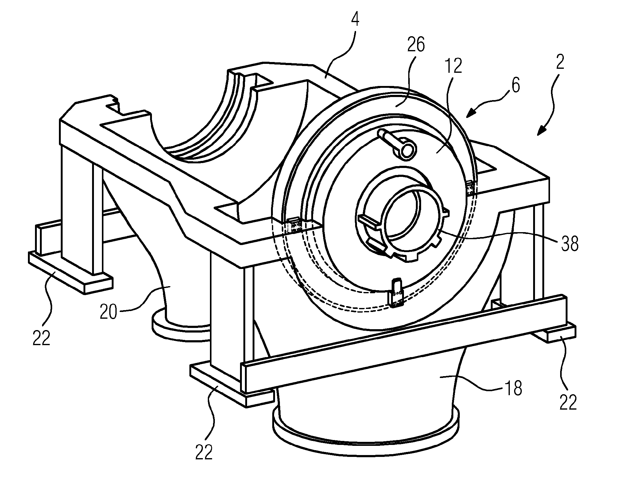
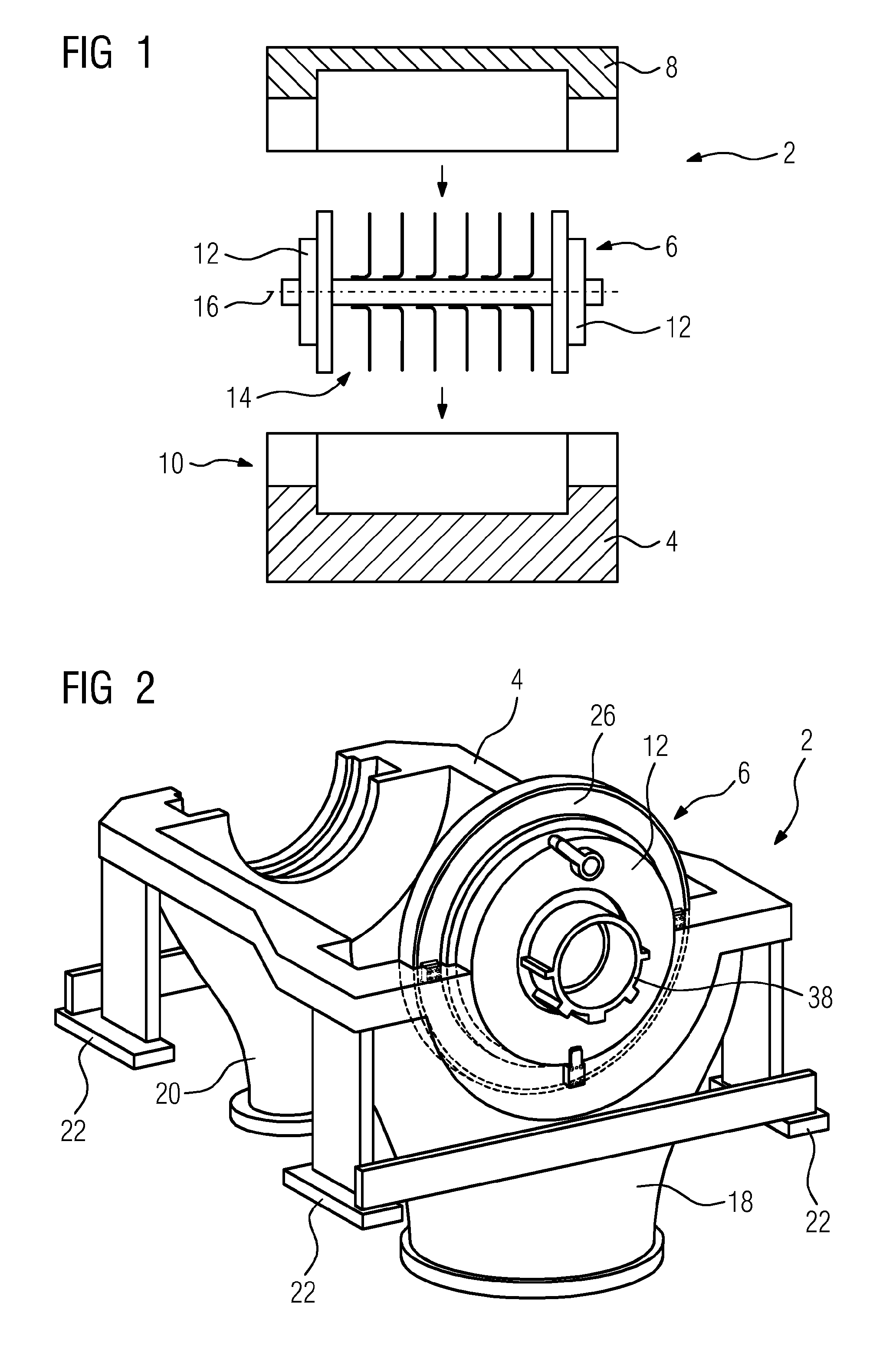
[0031]In large turbomachines, the housing is divided into a lower housing part and an upper housing part. In order to assemble the turbomachine, first of all the lower housing part is set up and then a rotor assemblage is inserted from above into the lower housing part. This is schematically illustrated in FIG. 1. The lower housing part 4 of the turbomachine 2 stands on a solid underlying surface and the assemblage 6 is lowered from above into the lower housing part 4. Subsequently, the upper housing part 8 is placed onto the lower housing part 4 and screwed together therewith, resulting in the overall housing 10. The assemblage is surrounded by the housing 10, wherein two covers 12 of the assemblage 6 remain visible from the outside and can also be designated part of the housing 10. The two covers 12 are in turn connected to the rotor 14, the shaft 16 of which is guided through the two covers 12 and is sealed off in the two covers 12 by way of a shaft seal (not illustrated). The ro...


PUM


Abstract

A turbomachine, comprising a lower housing part, an assembly inserted into the lower housing part from above, comprising two opposite housing covers and a rotor having a shaft, the rotor being fed through both housing covers, and an upper housing part that encloses the assembly from above and is fastened to the lower housing part, is provided. A shaft seal is arranged between the cover and the shaft. To maintain good function of the shaft seal during operation using cold or hot gases, at least one of the covers has a temperature-control means guided around the shaft, having a first and a second temperature-control channel, for controlling the temperature of the lid in the area around the shaft.

Description

CROSS-REFERENCE TO RELATED APPLICATIONS[0001]This application claims priority to PCT Application No. PCT / EP2013 / 053911 having a filing date of Feb. 27, 2013, based off of DE 102012203144.8 having a filing date of Feb. 29, 2012, the entire contents of which are hereby incorporated by reference.FIELD OF TECHNOLOGY[0002]The following relates to a turbomachine having a lower housing part, an assemblage—which is placed in the lower housing part from above and comprises two mutually opposing housing covers and a rotor, guided between the two housing covers, having a shaft—and an upper housing part, which encloses the assemblage from above and is secured to the lower housing part.BACKGROUND[0003]Turbomachines are used to expand or compress gases. Thus, in the case of a turbine, inlet gases are introduced into the turbine at high pressure and expand there, giving off energy to the rotor. Compressors, on the other hand, are used to compress air or other gases to final pressures of up to 100 ...

Claims


Application Information

Patent Timeline
Patent Type & Authority Applications(United States)
IPC IPC(8): F04D29/58F04D29/063F04D29/40F04D19/02F04D29/08
CPCF04D29/584F04D19/02F04D29/063F04D29/403F04D29/083F04D17/122F04D29/4206F04D29/522
Inventor KLETT, RICARDAMURANYI, ERICHNASS, DIETERSENYK, GREGOR
Owner SIEMENS AG
Why Eureka
Try Eureka