Intake filter for an internal combustion engine of a motor vehicle

a technology for internal combustion engines and filters, which is applied in the direction of combustion-air/fuel-air treatment, separation processes, and filtration separation, etc., can solve the problems of inconsiderable weight to the engine hood, rigid housing of air filters, and achieve reduced intake noise of internal combustion engines, short overall length, and large effective filter surface

Inactive Publication Date: 2007-06-14
MANN HUMMEL GMBH
View PDF31 Cites 10 Cited by
  • Summary
  • Abstract
  • Description
  • Claims
  • Application Information

AI Technical Summary

Benefits of technology

[0013] To prevent the intake of hot engine exhaust, in one advantageous embodiment of the invention, the tubular body may be provided with a cover. This cover ensures that the fresh air to be drawn in flows in at defined points, as for example in the upper area of the radiator grille, and is supplied to the intake filter. The cover also may have acoustic properties, so that it helps reduce the intake no

Problems solved by technology

One drawback of this device is that the housing of the air filter is a rigid structure.
In addition, a special hou

Method used


Image

  • Intake filter for an internal combustion engine of a motor vehicle
  • Intake filter for an internal combustion engine of a motor vehicle
  • Intake filter for an internal combustion engine of a motor vehicle

Examples


Embodiment Construction

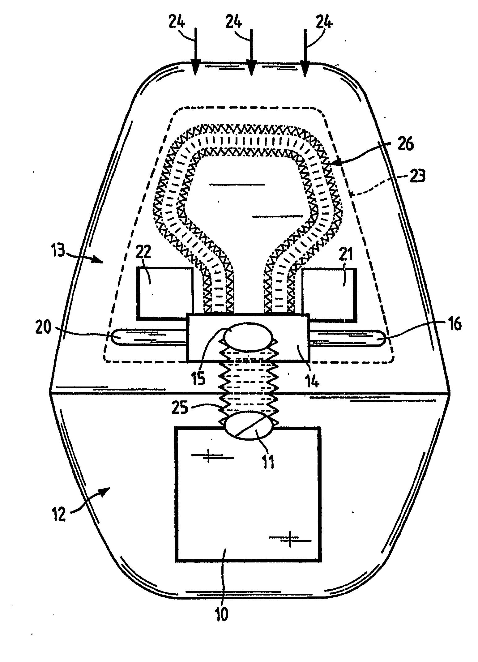
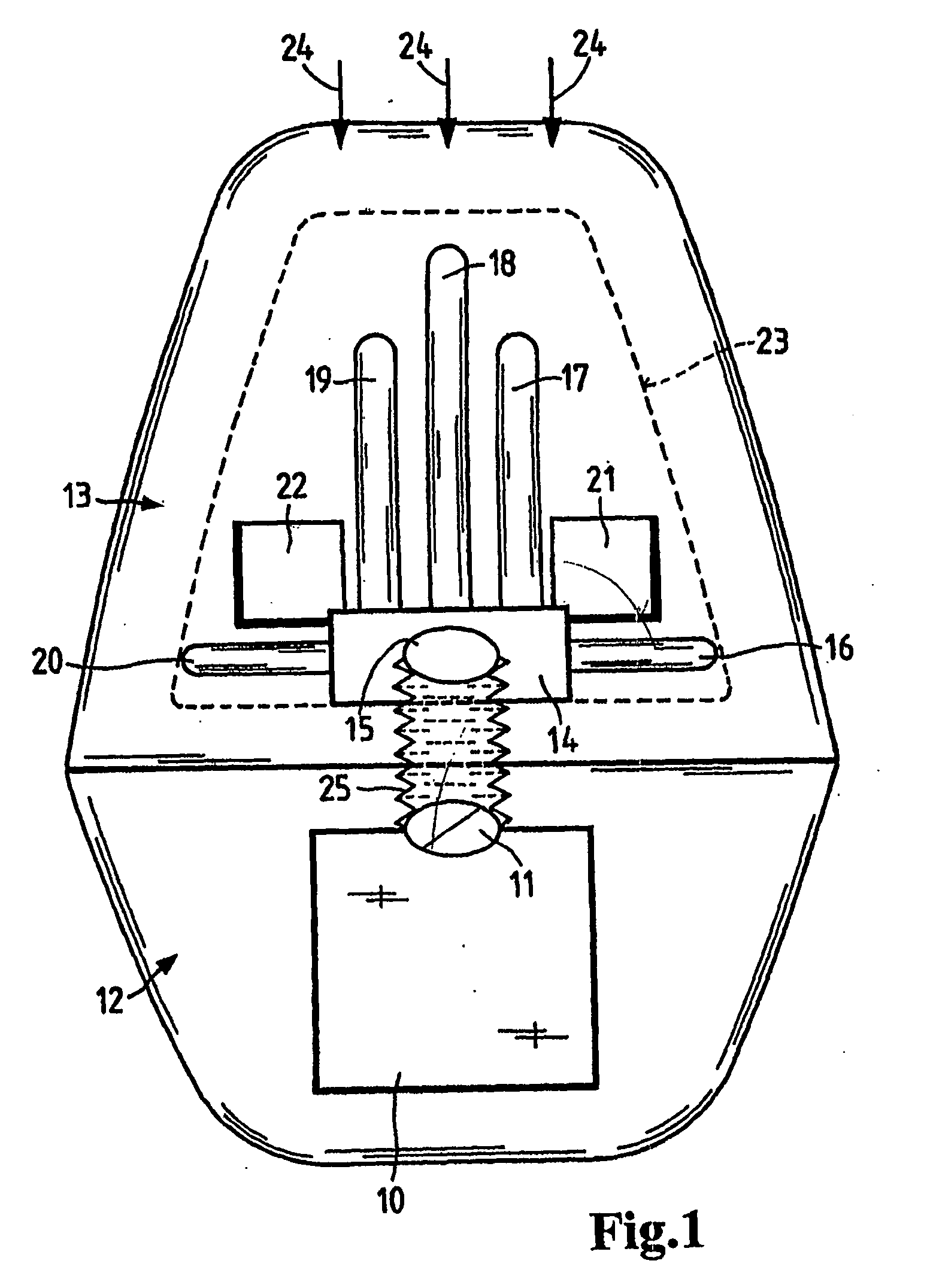
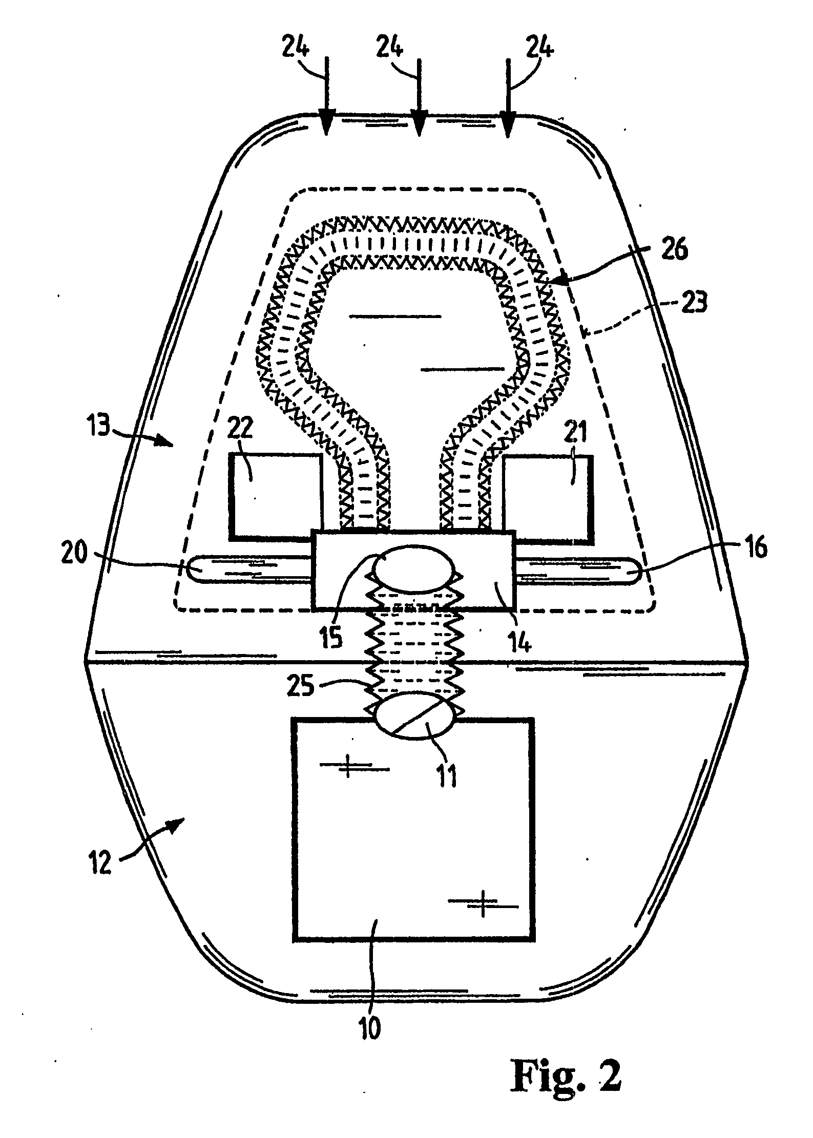
[0023]FIG. 1 schematically illustrates the engine 10 of a motor vehicle. On this engine 10, there is an opening 11 through which the intake air flows in and from where it is distributed to the individual cylinders of the engine. An engine hood 13 is arranged on top of the engine compartment 12. In FIG. 1 the engine hood is shown open so that the underside of the hood is visible. On the underside of hood 13 there is a plenum chamber 14 with a filtered air opening 15. This plenum chamber in turn has openings to the outside, which communicate with tubular filter elements (tubular filters 16, 17, 18, 19, 20). These tubular filters each have a round or oval cross section and are likewise depicted only schematically. In addition to the tubular filters, resonance chambers 21 and 22 are provided, which communicate with the plenum chamber 14 through openings and which are appropriately configured to dampen the intake air noise. The tubular filters and the resonance chambers are covered relat...


PUM

PropertyMeasurementUnit
Diameteraaaaaaaaaa
Flexibilityaaaaaaaaaa
Porosityaaaaaaaaaa

Abstract

An intake filter for an internal combustion engine for a motor vehicle including an unfiltered air intake region, a filter medium and a filtered air conduit, in which the unfiltered air intake region is arranged beneath the engine hood of the motor vehicle and is attached to the engine hood. The filter medium is tubular body which has a porosity that ensures a sufficient filtration of the intake air for the internal combustion engine.

Description

CROSS REFERENCE TO RELATED APPLICATIONS [0001] This application is a continuation of international patent application no. PCT / EP2005 / 051486, filed Mar. 31, 2005 designating the United States of America and published in German on Oct. 13, 2005 as WO 2005 / 095783, the entire disclosure of which is incorporated herein by reference. Priority is claimed based on Federal Republic of Germany patent application no. DE 10 2004 016546.7, filed Mar. 31, 2004. BACKGROUND OF THE INVENTION [0002] The invention relates to an intake filter for an internal combustion engine of a vehicle comprising a dirty air intake area, a filter medium and a clean air pipe, wherein the dirty air intake area is disposed on the underside of the engine hood of the vehicle and is connected thereto. [0003] U.S. Pat. No. 4,932,490 discloses a vehicle with an internal combustion engine. To supply the intake air for the internal combustion engine, an unfiltered air passage is provided on the engine hood to receive the air ...

Claims


Application Information

Patent Timeline
IPC IPC(8): F02M35/02F02M25/00F02B77/04B01D46/04B01D46/10B01D46/52B60K13/02F02M35/024F02M35/04F02M35/16
CPCB01D46/04B01D46/10B01D46/4236B01D46/521B01D46/525B01D2279/60B60K13/02F02M35/024F02M35/04F02M35/161Y10S55/28
Inventor MOSER, NIKOLAUSFRANZ, ANDREASSCHIMPF, BIRGITHAMMERSCHICK, JOERGWALTENBERG, KLAUSWEISSENBACHER, EMESESCHUSTER, MATHIASCEDZICH, WOLFGANGBUEHL, HEINZSTEUSS, ANDREASWERNER, JUERGENSPAETH, HARALDGRADL, MATTHIASLECHNER, MICHAELLINDE, HANSJUERGENNEUMANN, UWE
Owner MANN HUMMEL GMBH
Why Eureka
Try Eureka