The thickness of the plate shown in FIG. 5 of this document is approximately one-fifth of the distance between the cameras, which makes such a structure very heavy, which may not be suitable for use in a system with wide-baseline
stereo cameras.
A problem with such existing
stereo camera systems is that individual camera modules (sometimes referred herein to as “camera sensors” or simply “cameras”) may shift and / or rotate with respect to each other over time, which may make initial calibration parameters become inaccurate over time.
For some stereo camera systems, a relative
camera orientation rotation of only 0.05 degrees can ruin the calibration of the system.
Moreover, in a conventional stereo camera system, there is potential for movement of, e.g., lens holders relative to circuit boards and / or other camera components, for relative pointing between camera modules to change, and also for positions of the circuit boards and the frame itself to change over time.
The multiple interfaces between components in a conventional stereo camera system make it likely that vibration, shock, and even
thermal expansion between components will cause the
field of view of the cameras in a stereo camera system to shift over time.
The relative movement of the camera components may invalidate the initial factory calibration of the system, which may make stereo vision data obtained by the system unreliable.
Such calibration problems have not been addressed or even recognized in the prior art because prior-art stereo vision systems typically have either been laboratory systems, which generally are not subjected to shocks or vibrations, or have been used in situations such as short-range indoor
robotics, which generally are not situations where highly accurate calibration is regarded as being critical.
The inherent susceptibility of conventional stereo vision systems to losing calibration has therefore not been recognized as a particular problem to be solved, because conventional systems have been limited to short baseline lengths and utilize large mechanical stiffeners.
Sparse keypoint approaches can fail when keypoints are incorrectly matched between images from the first and second cameras, which can happen in image scenes with repeating structures (e.g., picket fences, building windows, etc.).
Furthermore, sub-pixel accuracy of feature points may be required to obtain camera parameters with sufficient accuracy for long-baseline and long-range operation, which is often not possible with smooth or rounded features, or with slightly defocused or blurred images.
Conventional structure-from-motion calculations generally are not fast enough to compensate for calibration errors from frame to frame, and thus typically are appropriate for slow perturbations of short-baseline stereo vision systems.
Another problem with sparse keypoint approaches is the sparse sampling of an image, which does not provide enough information to determine the intrinsic or extrinsic camera parameters accurately.
This clustered sampling does not provide enough information to determine with high accuracy the relative orientation of the
stereo cameras (an extrinsic camera parameter), much less lens
distortion coefficients (an intrinsic camera parameter), which are sensitive to distortions at the edges of the image.
In other words, these conventional techniques do not compensate for camera parameters that may be important for proper calibration of a stereo vision system.
The method does not correct for roll errors or for a relative translation vector between the equipment's two cameras.
Furthermore, the method requires straight and reliable road paint markings, which may not be available or may be obstructed by
snow or faded by wear or sun exposition, thus limiting angular accuracy of the equipment's calibration.
One
disadvantage of this system is that it requires IMU hardware and cannot correct for camera position from a video
stream alone.
Another
disadvantage is that the IMUs can be used to compensate for fast perturbations but not for slow perturbation (e.g., a slow drift of positions of the cameras), which means that the cameras may need to be manually calibrated on a frequent basis (e.g., daily).
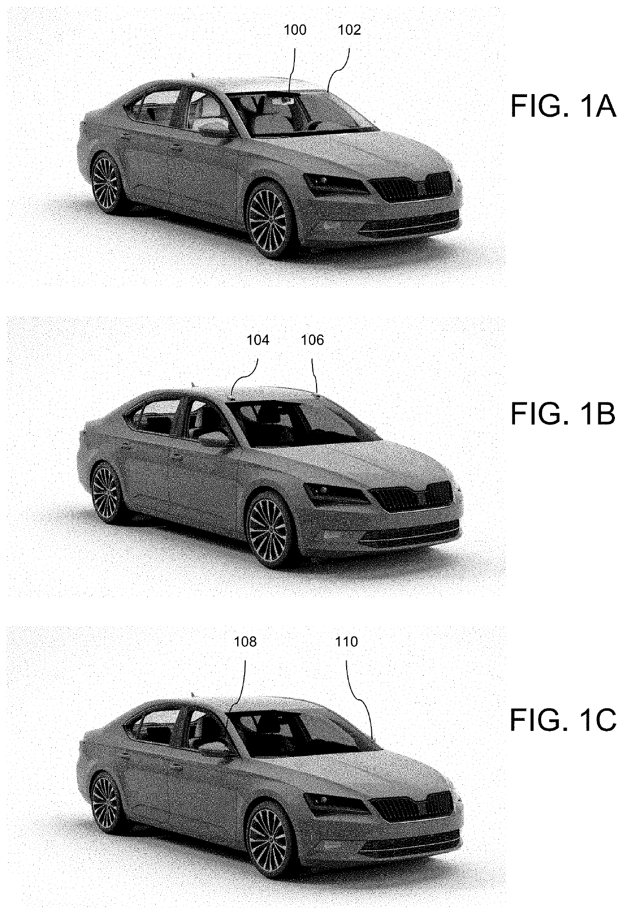
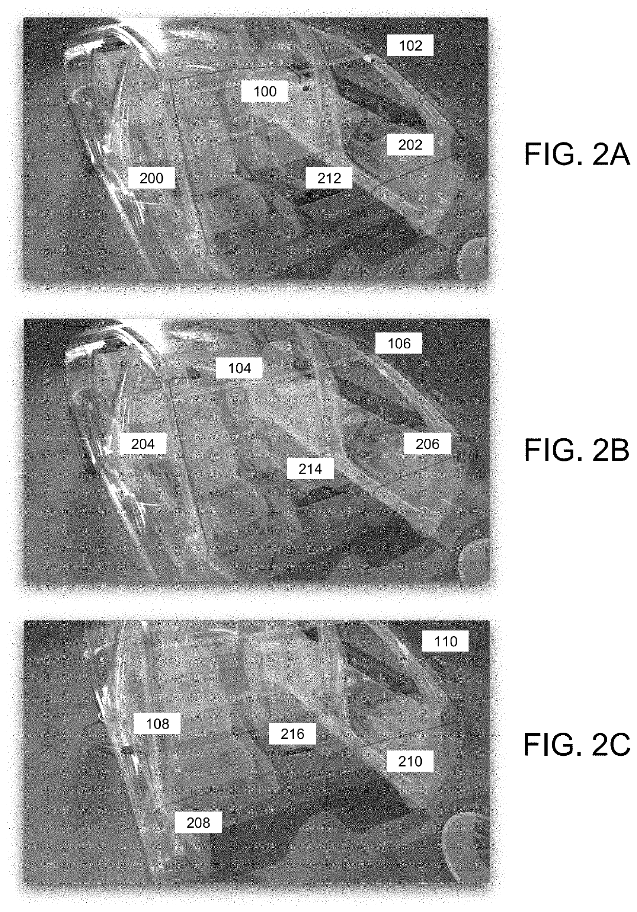
The calibration problems described above may be exacerbated in long-baseline stereo vision systems, where the distance between camera modules is, e.g., greater than approximately 20 cm, and in systems where it is not possible to connect two or more camera modules with heavy structural beams or mounting members.
However, these locations are not sufficiently rigid to maintain calibration over hours or days, much less a 15-year lifetime of a typical vehicle.
In some cases, it may not be realistically possible to add rigid mechanical support structures between the headlights, the upper corners of the
windshield, and the side-view mirrors, because a shortest path for these support structures may be blocked by an engine block, may block a driver's view, and may be blocked by the driver himself / herself, respectively.
Furthermore, even if supporting structures could be added, a thickness and weight of such structures required to provide adequate structural support may be impractical.
This scaling has resulted in commercially available stereo vision systems to be physically limited to baselines of less than 20 cm.
The processor hardware required to achieve the needed computational speed may be costly and may add unwanted complexity to the system; (3) accuracy: a calibration accuracy needed for long-baseline systems may be much greater than for short-baseline systems, because greater angular accuracies are required to estimate targets at longer distances; and (4) completeness: whereas conventional techniques for automatic calibration of
stereo cameras may compensate for a few camera parameters (e.g., the relative orientation of the stereo cameras), a full calibration would require compensating for all extrinsic and intrinsic camera parameters.
Prior to the technology presented herein, a system that addresses these four reasons has not yet been achieved.

