Dielectric resonator, dielectric filter, and method of supporting dielectric resonance element
a dielectric filter and dielectric resonator technology, applied in the direction of resonators, basic electric elements, waveguide devices, etc., can solve the problems of increasing manufacturing difficulty and manufacturing cost, difficult to realize stable resonators and filters, and difficult to realize high-performance dielectric resonators and filters
- Summary
- Abstract
- Description
- Claims
- Application Information
AI Technical Summary
Benefits of technology
Problems solved by technology
Method used
Image
Examples
embodiment 1
(Embodiment 1)
[0096]A dielectric resonator in Embodiment 1 of the present invention will be described with reference to the drawings.
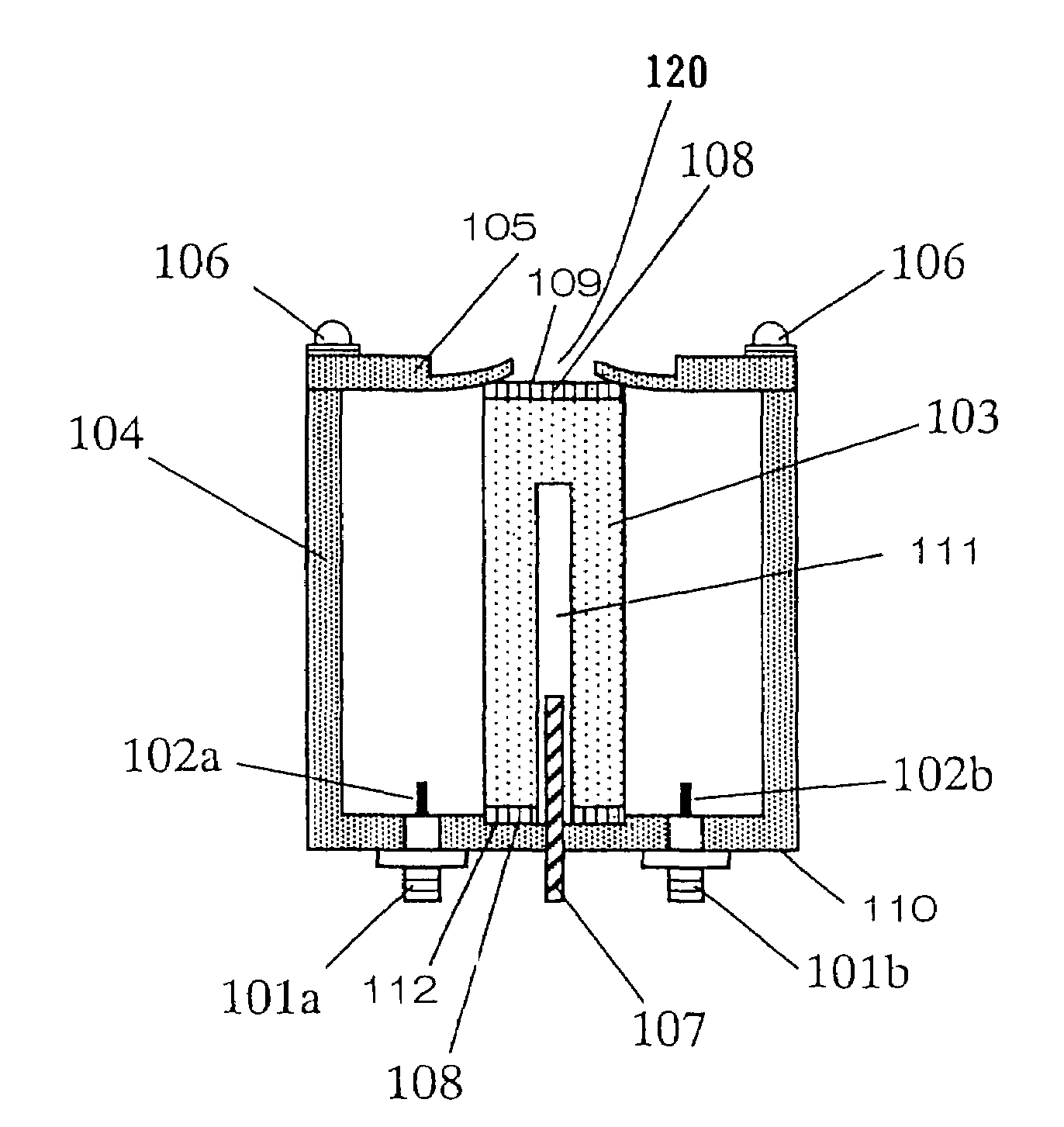
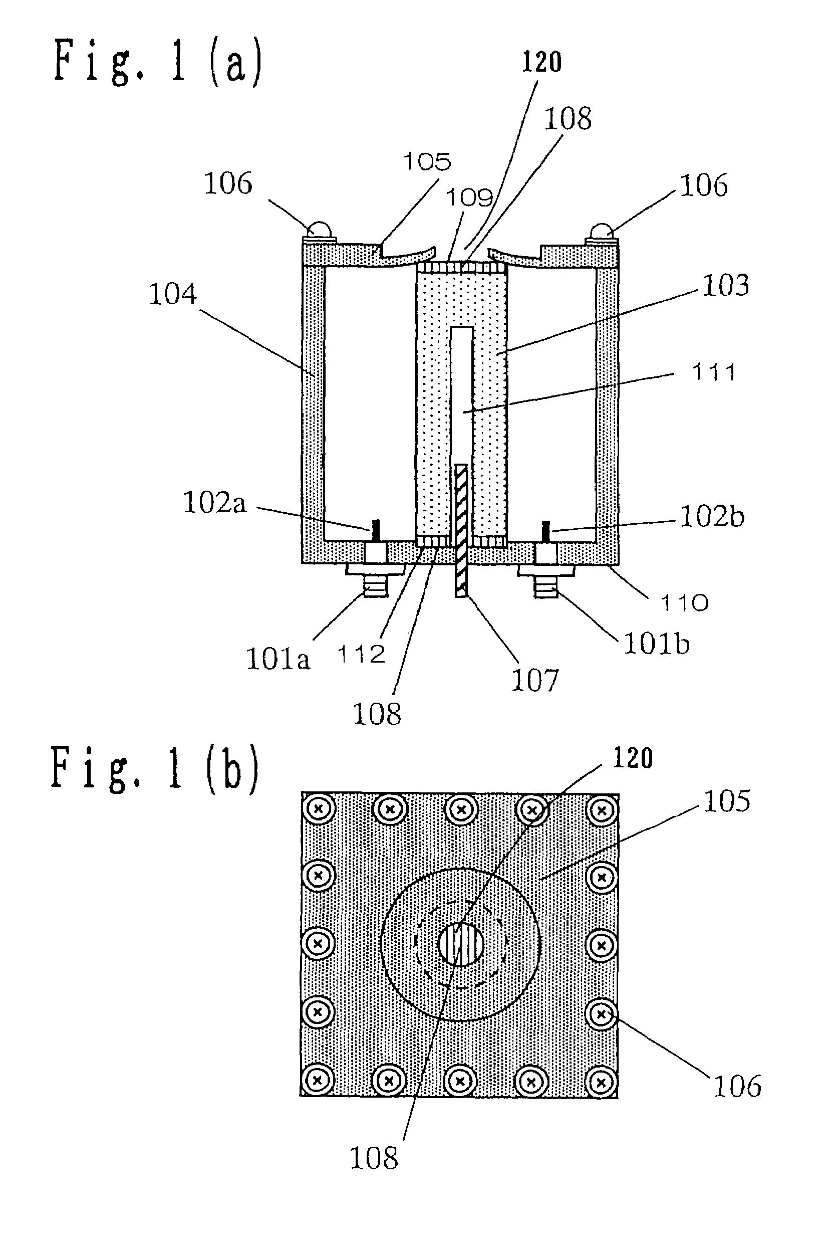
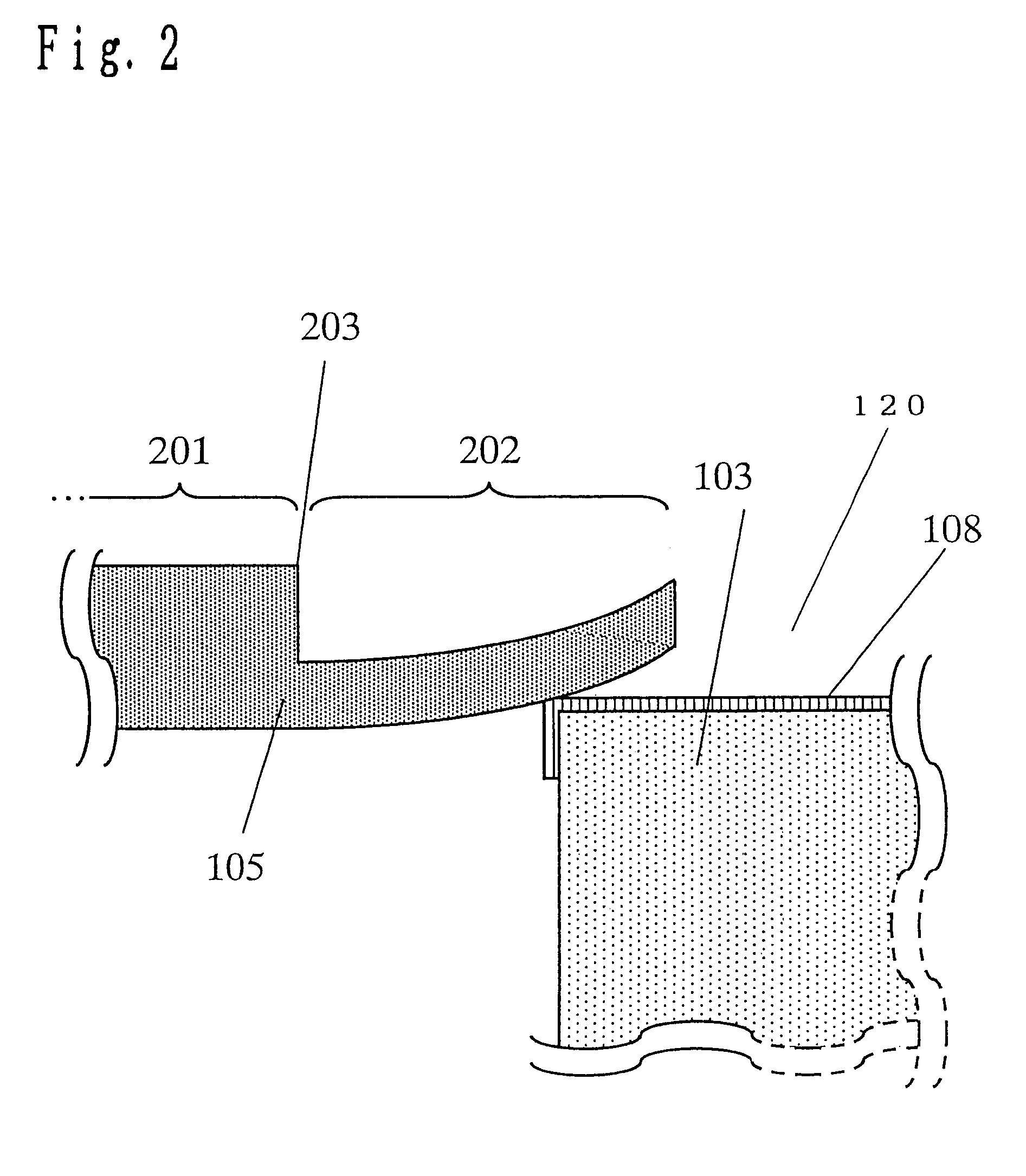
[0097]FIG. 1(a) is a cross-sectional view of a TM mode dielectric resonator in Embodiment 1 of the present invention. FIG. 1(b) is a top view of the dielectric resonator. FIG. 2 is an enlarged sectional view of a metalized surface 108, which is an example of the electroconductive film in accordance with the present invention in a dielectric resonance element, and which is provided in a dielectric resonance element 103 used in the dielectric resonator in Embodiment 1 of the present invention. Referring to FIGS. 1(a), 1(b), and 2, the dielectric resonator includes input / output terminals 101a and 101b, input / output probes 102a and 102b, a dielectric resonance element 103, a metallic casing 104, a metallic cover 105, connecting screws 106, a frequency adjusting screw 107, and the metalized surface 108, and the metallic cover 105 has a thick portion 201 and...
embodiment 2
(Embodiment 2)
[0119]A dielectric resonator in Embodiment 2 of the present invention will be described with reference to the drawing.
[0120]FIG. 6 is a cross-sectional view of a TM mode dielectric resonator in Embodiment 2 of the present invention. Description of the same portions as those in Embodiment 1 will not be repeated. Referring to FIG. 6, the dielectric resonator includes copper foil 401, which is an example of the thin film in accordance with the present invention, solder 402, and a cover 403.
[0121]As shown in FIG. 6, a metalized surface 108 at the lower end of a dielectric resonance element 103 and a bottom surface 110 of a metallic casing 104 are electrically connected to each other by solder 402. Copper foil 401 is provided at the upper end of the dielectric resonance element 103, and the copper foil 401 and the metalized surface 108 at the upper end of the dielectric resonance element 103 are electrically connected to each other by solder 402. The copper foil 401 and the...
embodiment 3
(Embodiment 3)
[0128]A dielectric resonator in Embodiment 3 of the present invention will be described with reference to the drawing.
[0129]FIG. 7 is a cross-sectional view of a TM mode dielectric resonator in Embodiment 3 of the present invention. Description of the same portions as those in Embodiments 1 and 2 will not be repeated.
[0130]As shown in FIG. 7, a thin portion 522 is provided in a metallic cover 501, a metalized surface 108 at the lower end of a dielectric resonance element 103 and a bottom surface 110 of a metallic casing 104 are electrically connected to each other by solder 402, and the metalized surface 108 at the upper end of the dielectric resonance element 103 and the thin portion 522 of the metallic cover 501 are electrically connected to each other by using solder 402.
[0131]Also in the thus-arranged dielectric resonator, the difference between the vertical lengths of the metallic casing 104 and the dielectric resonance element 103 at the time of expansion / contrac...
PUM
 Abstract
Description
Claims
Application Information
 - R&D
- Intellectual Property
- Life Sciences
- Materials
- Tech Scout
- Unparalleled Data Quality
- Higher Quality Content
- 60% Fewer Hallucinations
Browse by: Latest US Patents, China's latest patents, Technical Efficacy Thesaurus, Application Domain, Technology Topic, Popular Technical Reports.
© 2025 PatSnap. All rights reserved.Legal|Privacy policy|Modern Slavery Act Transparency Statement|Sitemap|About US| Contact US: help@patsnap.com


