Dielectric-resonator array antenna system

a technology of dielectric resonance array and antenna system, which is applied in the direction of antennas, radiating element structural forms, and antenna adaptation in movable bodies, etc., can solve the problems of increasing fuel consumption, reducing the flying range of aircraft, and increasing air drag for the aircraft on which the antenna system is mounted, so as to minimize interference and wide bandwidth , the effect of high gain

Inactive Publication Date: 2005-12-01
EMS TECH CANADA
View PDF31 Cites 36 Cited by
  • Summary
  • Abstract
  • Description
  • Claims
  • Application Information

AI Technical Summary

Benefits of technology

[0008] The invention provides a dielectric resonator element array (DRA) antenna system that is small, compact, has high gain in the direction of intended communication, minimized interference in unintended directions of communication and a wide bandwidth. The antenna system comprises a ground plane, a feed structure, a beam shaping and steering controller, a mounting apparatus, an array of dielectric resonator elements and a radome that is close to or in contact with the array. The mounting apparatus preferably is configured so as not to appreciably increase the size of the system when the antenna system is mounted on the object. Therefore, the radome does not appreciably increase drag and does not adversely affect the aesthetic appearance of the object on which it is mounted.

Problems solved by technology

Aeronautical antenna systems for satellite communications can be very large in area, which results in increased air drag and more weight for the aircraft on which the antenna system is mounted.
Increased drag and weight result in a reduction in the aircraft's flying range, increased fuel consumption and corresponding higher aircraft operational costs.
Large antenna systems can also increase lightning and bird strike risks, as well as degrade the visual aesthetics of the aircraft.
The configuration of crossed-dipole elements is relatively tall, which results in high drag.
The microstrip patch element has a relatively low profile, but has both a narrow beamwidth and narrow bandwidth, which restrict the antenna's performance.
The narrow beamwidth of the patch element results in excessive gain reduction and impedance mismatch when the array beam peak is scanned toward the aircraft horizon with the antenna mounted on the top of the fuselage.
The narrow bandwidth of the patch radiator makes the impedance mismatch more catastrophic at extreme scan angles.
These effects reduce the gain of the antenna system, thus requiring that the antenna have a larger antenna footprint and overall larger size.
This current approach to determining element phase settings does not minimize interference with other satellites on the geosynchronous arc.
The Omnipless HGA 7000 antenna system has not yet been sold commercially and is of unknown construction.

Method used


Image

  • Dielectric-resonator array antenna system
  • Dielectric-resonator array antenna system
  • Dielectric-resonator array antenna system

Examples


Embodiment Construction

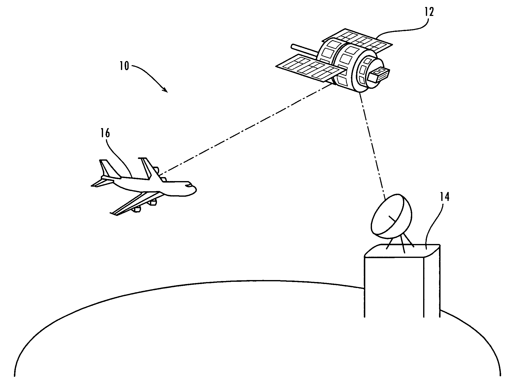
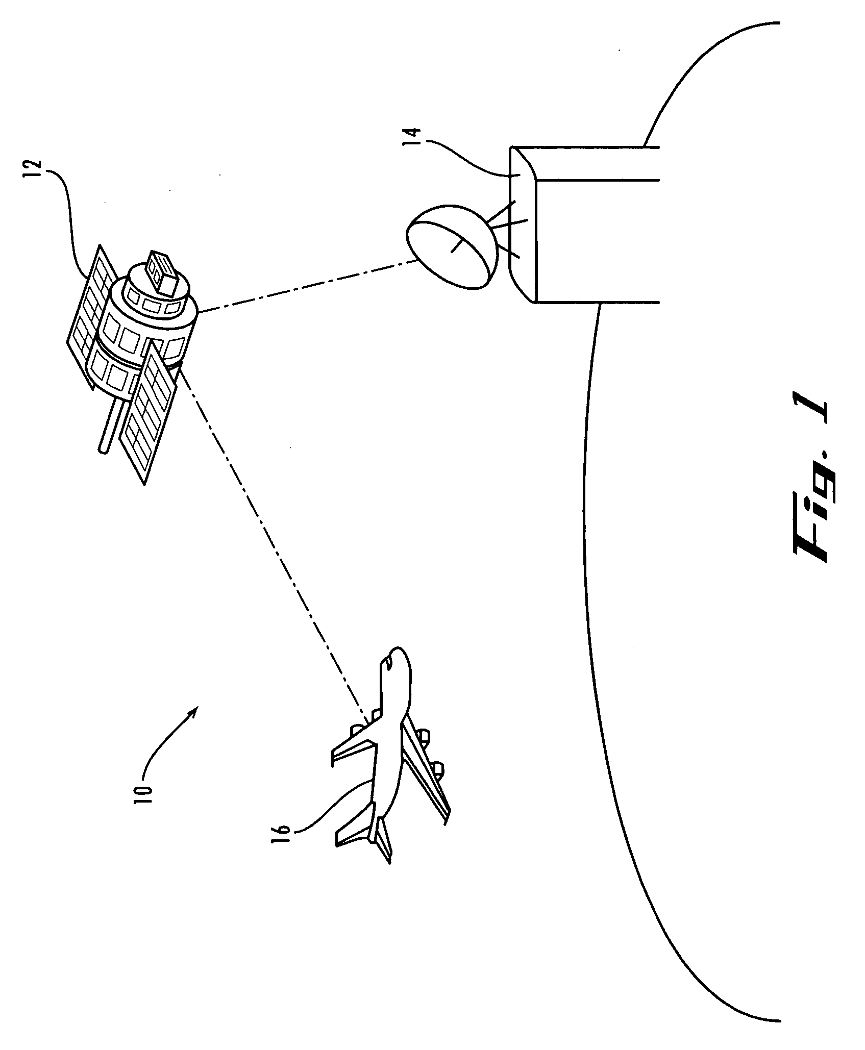
[0019] The dielectric resonator element array (DRA) antenna system of the invention is well suited for use in a wide range of applications, particularly for data, voice and video satellite communications, and more particularly, for communication with Inmarsat satellites. However, the antenna system of the present invention is not limited to any particular uses or technological environments. FIG. 1 is a pictorial illustration of the DRA antenna system of the invention being employed in an aeronautical environment 10. An Inmarsat satellite 12 provides a communication link between a terrestrial transceiver 14 and an airplane 16 on which the DRA antenna system (not shown) is attached. It should be noted that the DRA antenna system of the invention could also be employed on the satellite 12. It should also be noted that the DRA antenna system may be communicating with fixed or mobile terrestrial transmitters receivers as opposed to, or in addition to, communicating with satellites.

[0020...


PUM


Abstract

A dielectric resonator element array (DRA) antenna system that is small, compact, has high gain in the direction of intended communication, minimized interference in unintended directions of communication and a wide bandwidth. The antenna system comprises a ground plane, a feed structure, a beam shaping and steering controller, a mounting apparatus, an array of dielectric resonator elements and a radome that is close to or in contact with the array. The mounting apparatus preferably is configured so as not to appreciably increase the size of the system when mounted. The controller receives and processes information relating to one or more of object latitude, longitude, attitude, direction of travel, intended direction of communication and unintended directions of communication. The controller processes this information and determines excitation phase for the array elements.

Description

TECHNICAL FILED OF THE INVENTION [0001] The invention relates to antennas and, more particularly, to a dielectric-resonator array antenna system that is small and low in profile, while also having a wide bandwidth, accurate beam steering and efficient radiation. BACKGROUND OF THE INVENTION [0002] Aeronautical antenna systems for satellite communications can be very large in area, which results in increased air drag and more weight for the aircraft on which the antenna system is mounted. Increased drag and weight result in a reduction in the aircraft's flying range, increased fuel consumption and corresponding higher aircraft operational costs. Large antenna systems can also increase lightning and bird strike risks, as well as degrade the visual aesthetics of the aircraft. [0003] Communications with satellites using physically small antenna arrays requires an exceptionally low noise temperature and high aperture efficiency. In aeronautical applications, the antenna should also be nar...

Claims


Application Information

Patent Timeline
Patent Type & Authority Applications(United States)
IPC IPC(8): H01Q1/28H01Q1/38H01Q9/04H01Q21/06
CPCH01Q1/288H01Q21/064H01Q9/0485
Inventor STRICKLAND, PETER C.
Owner EMS TECH CANADA
Why Eureka
Try Eureka