Dielectric resonator antenna with a caved well

a technology of dielectric resonator and caved well, which is applied in the direction of antennas, antenna details, antenna earthings, etc., can solve the problems of increasing the complexity of the manufacturing process and the cost, and the bandwidth is limited, and achieves the effects of simple structure, easy manufacturing, and small siz

Inactive Publication Date: 2007-11-06
NAT TAIWAN UNIV
View PDF9 Cites 35 Cited by
  • Summary
  • Abstract
  • Description
  • Claims
  • Application Information

AI Technical Summary

Benefits of technology

[0012]Therefore, according to the present invention, the rectangular parallelepiped resonator is made of a dielectric material and provided with a rectangular caved well, which may achieve 34% bandwidth. Also the dielectric resonator antenna has advantages of small size, simple structure and easy to manufacture. In the meantime, using a microstrip as the signal line and using coupled slot to feed in the antenna make the dielectric resonator antenna easy to integrate with other planar circuit, and reduce interference between the antenna and the other components.

Problems solved by technology

However, it is a resonator antenna, and its bandwidth is limited.
All these methods increase the complexity of the manufacturing process and the cost.

Method used


Image

  • Dielectric resonator antenna with a caved well
  • Dielectric resonator antenna with a caved well
  • Dielectric resonator antenna with a caved well

Examples


Embodiment Construction

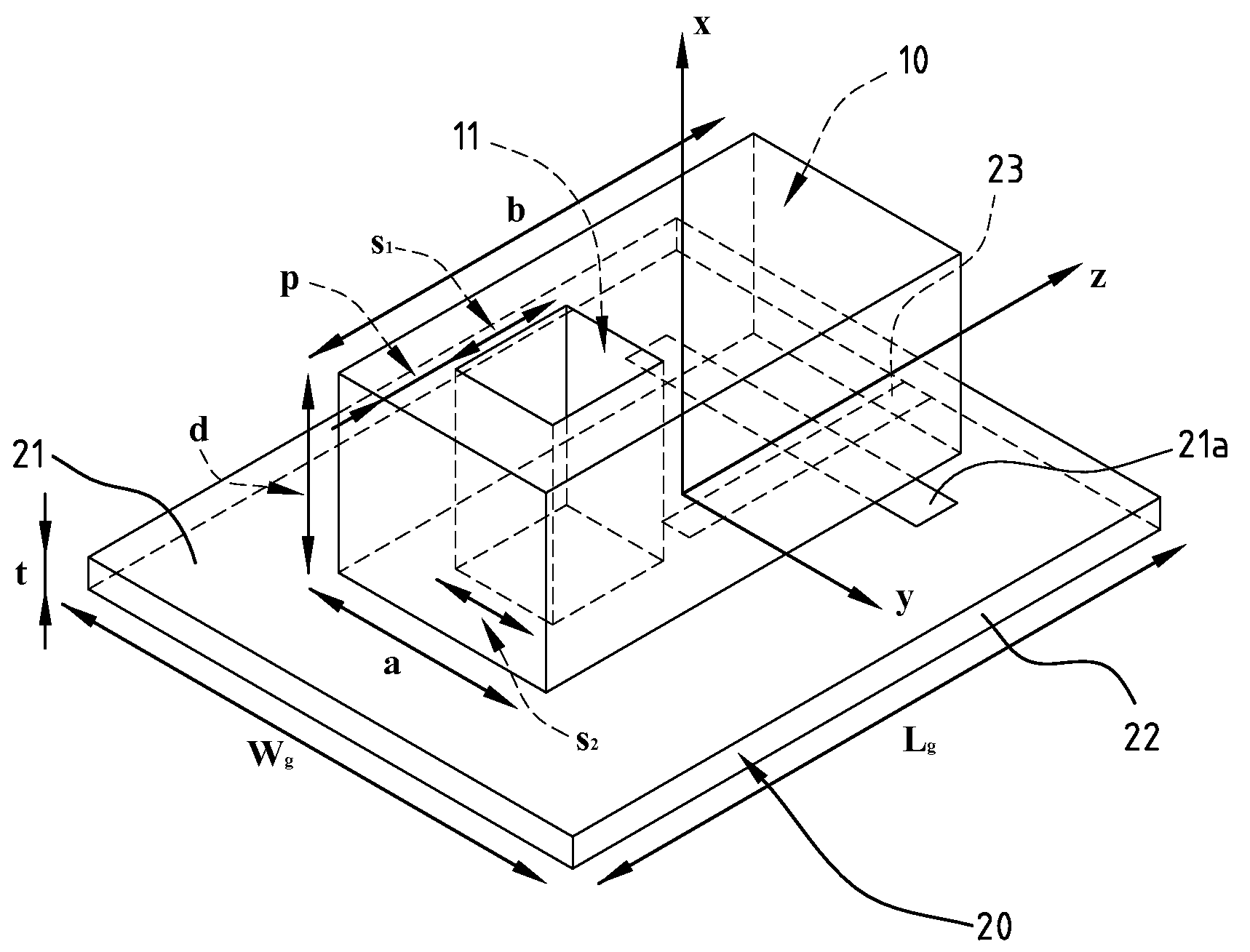
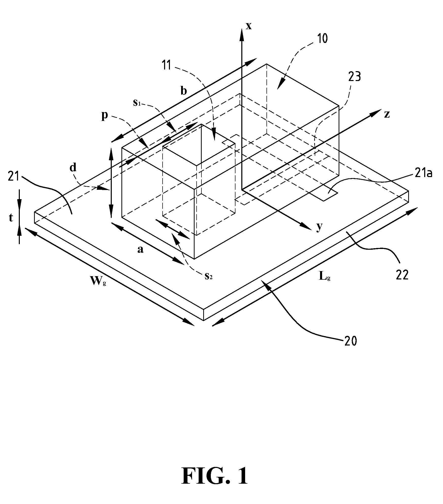
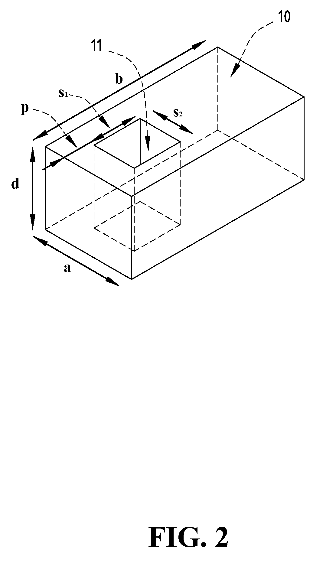
[0020]With reference to the drawings and in particular to FIGS. 1, 2 and 3, a dielectric resonator antenna in accordance with the present invention comprises a dielectric resonator 10 receiving or transmitting signals of specific bandwidth and a feed-in / feed-out component 20. Wherein, the dielectric resonator 10 is a rectangular parallelepiped made of a dielectric, and a rectangular cavity passing through from the top surface to the bottom surface of the dielectric resonator 10 to form a caved well 11. The dielectric resonator 10 is made of dielectric materials including low-temperature co-fired ceramics and materials with high dielectric constants. The feed-in / feed-out component 20 is a dielectric substrate 22 whose top surface and bottom surface are coated with a ground metal layer 21 and a strip metal layer 23, respectively.

[0021]The dielectric substrate 22 of the feed-in / feed-out component 20 is made of dielectric materials such as FR4, Teflon, Duriod, fiberglass, aluminum oxide...


PUM


Abstract

A dielectric resonator antenna is a dielectric resonator mounted on a feed-in/feed-out component. The dielectric resonator is a rectangular parallelepiped made of a dielectric, and has a caved well passing through from the top surface to the bottom surface thereof. The feed-in/feed-out component includes a dielectric substrate, a ground metal layer and a strip metal layer coated on the top surface and the bottom surface, respectively, of the dielectric substrate. An etched part is provided on the ground metal layer. Wherein, the dielectric resonator with the caved well is mounted on the ground metal layer of the feed-in/feed-out component.

Description

BACKGROUND OF THE INVENTION[0001]1. Field of the Invention[0002]The present invention relates to a dielectric resonator antenna, and in particular to a rectangular dielectric resonator, of which part of the dielectric is removed to form a rectangular caved well, for enhancing electric field and expanding bandwidth.[0003]2. The Prior Arts[0004]A conventional dielectric resonator antenna is usually made of a material with high dielectric constant and low loss. The dielectric resonator antenna has many advantages, for example, high radiation efficiency, simple structure, and various radiation patterns achieved by stimulating various modes. However, it is a resonator antenna, and its bandwidth is limited. Basically, the dimensions and shape of the antenna decide the operating frequency and the bandwidth of the resonator antenna.[0005]The means to increase the bandwidth of the dielectric resonator antenna include: (1) cutting off the apex of a conical dielectric resonator, making the sma...

Claims


Application Information

Patent Timeline
Patent Type & Authority Patents(United States)
IPC IPC(8): H01Q15/02
CPCH01Q9/0485
Inventor CHANG, TZE-HSUANKIANG, JEAN-FU
Owner NAT TAIWAN UNIV
Why Eureka
Try Eureka