Multimode dielectric resonator device, dielectric filter, composite dielectric filter and communication device

a dielectric resonator and dielectric filter technology, applied in waveguide devices, resonators, basic electric elements, etc., can solve the problems of coupling between the coupling between the tm mode and the tm mode also caused to arise, and it is difficult to independently determine the amount of coupling between the te mode and the te mod

Inactive Publication Date: 2006-06-29
MURATA MFG CO LTD
View PDF3 Cites 37 Cited by
  • Summary
  • Abstract
  • Description
  • Claims
  • Application Information

AI Technical Summary

Benefits of technology

[0014] With this structure, a frequency change in the even mode and the odd mode of the TM coupling mode, which arises by the difference in the amount of protrusion or the amount of subsidence of the dielectric core disposed on the position having a high electric flux density of the TE coupling mode, is canceled, and thus the coupling between the first and the second TM01δ modes or TM011 modes can be prevented.

Problems solved by technology

However, in a known multimode dielectric resonator device, there has been a problem in that coupling is also produced between the TM mode and the TM mode at the same time even if the shape of the dielectric core is determined only by paying attention to the portion on which two modes of electric fields to be coupled are concentrated in order to perform the coupling between the TE mode and the TE mode.
That is to say, in a multimode dielectric resonator using both the TM mode and the TE mode, when the coupling between the TE mode and the TE mode is performed, the coupling between the TM mode and the TM mode is also caused to arise, and thus it is difficult to independently determine the amount of coupling between the TE mode and the TE mode.
Thus, there has been a problem in that when a filter is constructed by coupling a plurality of resonant modes in sequence, the difficulty in adjusting the filter characteristics thereof increases.

Method used


Image

  • Multimode dielectric resonator device, dielectric filter, composite dielectric filter and communication device
  • Multimode dielectric resonator device, dielectric filter, composite dielectric filter and communication device
  • Multimode dielectric resonator device, dielectric filter, composite dielectric filter and communication device

Examples


first embodiment

[0044] A description will be given of a multimode dielectric resonator device with reference to FIGS. 1 to 10.

[0045] The material of the dielectric core disposed in the devices shown in each embodiment including this first embodiment is selected in accordance with the frequency band used for the device. For example, a selection is made from groups including zirconium titanate-stannum titanate series compounds, rare-earth barium titanate series compounds, barium titanate series compounds, zinc barium tantalate series compounds, magnesium barium tantalate series compounds, rare earth aluminate-calcium titanate series compounds, magnesium titanate-calcium titanate series compounds. The relative dielectric constant at this time has an arbitrary value between 20 to 130. A zirconium titanate-stannum titanate compound having a relative dielectric constant of 38 is used in this first embodiment and the other embodiments shown subsequently.

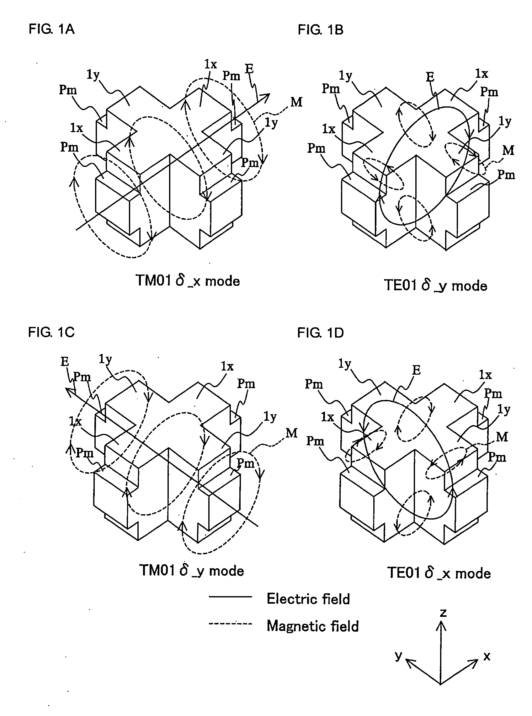
[0046]FIG. 1 is a perspective view showing a diele...

third embodiment

[0070]FIGS. 12 and 13 are diagrams illustrating the configuration of a dielectric filter according to a (A) of FIG. 12 is a plan view of the dielectric core 1 in the cavity 2 and (B) is a front view of the same dielectric core 1. This dielectric core 1 has a structure equal to the structure in which the middle-layer part Lb of the dielectric core 1 shown in FIG. 10 shifted to the lowermost to eliminate the lower-layer part Lc in order to have a two-layer structure consisting of an upper-layer part La and a lower-layer part Lb′. Accordingly, the probes 4a, 4b are also disposed in the central part of the lower-layer part Lb′ of the dielectric core 1. Even with this two-layer structure, the TE01δ_x mode and the TE01δ_y mode can be coupled by the protrusion of the protrusions Pe for TE coupling, and the coupling between the TM01δ_x mode and the TM01δ_y mode can be restrained by the protrusion of the protrusions Pc for restraining the TM coupling. Accordingly, the dielectric resonator d...

fifth embodiment

[0074]FIGS. 16 and 17 are diagrams illustrating the structure of a dielectric filter according to a The dielectric core 1 used in this dielectric filter is equal to a structure in which a dielectric core 1 shown in FIG. 14 is modified to have a cylindrical shape. That is to say, the dielectric core 1 has a substantially cylindrical shape as a whole, forming subsidences Se for the TE coupling on the upper-layer part La, and subsidences Sc for restraining the TM coupling on the lower-layer part Lb′. Also, FIG. 17 is equal to a structure in which the dielectric core protrusions Pm in FIG. 16 are removed. Even using such forms, the dielectric resonator device also operates as a dielectric filter consisting of four-stage resonators and having a band-pass characteristic.


PUM


Abstract

Two TE modes whose electric-field rotating planes have a perpendicular relationship are coupled independently of the coupling between two TM modes whose electric-field directions have the same respective perpendicular relationships. In a multimode dielectric resonator device producing four modes: TM01δ_x mode, TM01δ_y mode, TE01δ_x mode, and TE01δ_y mode, protrusions (Pe1), (Pe2) are disposed on an upper-layer (La) and a lower-layer of a dielectric core (1) to cause a difference in effective dielectric constants of individual parts through which even-mode and odd-mode electric flux of the TE coupling modes passes. A protrusion (Pc) is formed on a middle-layer Lb of the dielectric core (1) such that the effective dielectric constants of the parts through which even-mode and odd-mode electric flux of the TM coupling modes pass become substantially equal. Thereby, the TE01δ_x mode and TE01δ_y mode are coupled while restraining the coupling of the TM01δ_x mode and the TM01δ_y mode.

Description

TECHNICAL FIELD [0001] This invention relates to a dielectric resonator device operating in a multimode, and a dielectric filter, a composite dielectric filter and a communication apparatus which include the same. BACKGROUND ART [0002] Previously, Japanese Unexamined Patent Application Publication No. 11-145704 has disclosed a multimode dielectric resonator device having a dielectric core disposed in a cavity and using a plurality of TM modes and TE modes. [0003] In this multimode dielectric resonator device, when coupling is performed between predetermined modes by the shape of the dielectric core, perturbation on an electric field is performed by providing a groove or a hole at a portion on which electric fields to be coupled are concentrated in order to exchange energy between the resonance modes, thereby the coupling is performed. [0004] However, in a known multimode dielectric resonator device, there has been a problem in that coupling is also produced between the TM mode and t...

Claims


Application Information

Patent Timeline
Patent Type & Authority Applications(United States)
IPC IPC(8): H01P1/20H01P7/10H01P1/208H01P1/213
CPCH01P1/2086H01P1/2138H01P7/105
Inventor WADA, TAKAYAHATTORI, JUN
Owner MURATA MFG CO LTD
Why Eureka
Try Eureka