Antenna array

a technology of micro-wave antennas and arrays, applied in the field of micro-wave antenna arrays, can solve problems such as complex processes

Inactive Publication Date: 2006-09-12
LOCKHEED MARTIN CORP
View PDF5 Cites 11 Cited by
  • Summary
  • Abstract
  • Description
  • Claims
  • Application Information

AI Technical Summary

Problems solved by technology

Such a process is complex both in the machining of the individual horn elements, as well as in the alignment and interconnection of adjacent elements.

Method used


Image

  • Antenna array
  • Antenna array
  • Antenna array

Examples


Embodiment Construction

[0021]In the accompanying drawings, like items are indicated by like reference numerals.

[0022]This description of the preferred embodiments is intended to be read in connection with the accompanying drawings, which are to be considered part of the entire written description of this invention. In the description, relative terms such as “lower,”“upper,”“horizontal,”“vertical,”, “above,”“below,”“up,”“down,”“top” and “bottom” as well as derivative thereof (e.g., “horizontally,”“downwardly,”“upwardly,” etc.) should be construed to refer to the orientation as then described or as shown in the drawing under discussion. These relative terms are for convenience of description and do not require that the apparatus be constructed or operated in a particular orientation. Terms concerning attachments, coupling and the like, such as “connected” and “interconnected,” refer to a relationship wherein structures are secured or attached to one another either directly or indirectly through intervening ...


PUM


Abstract

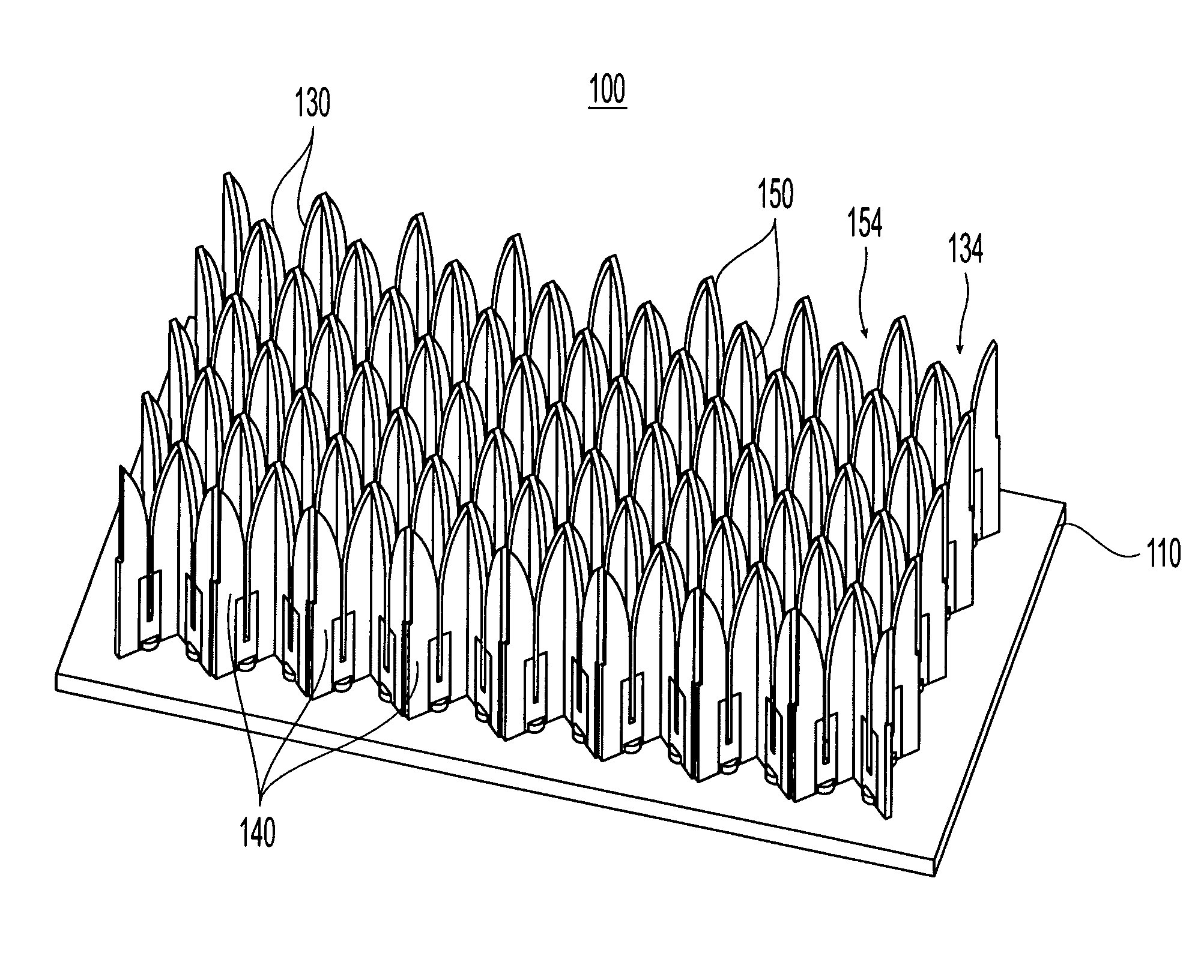
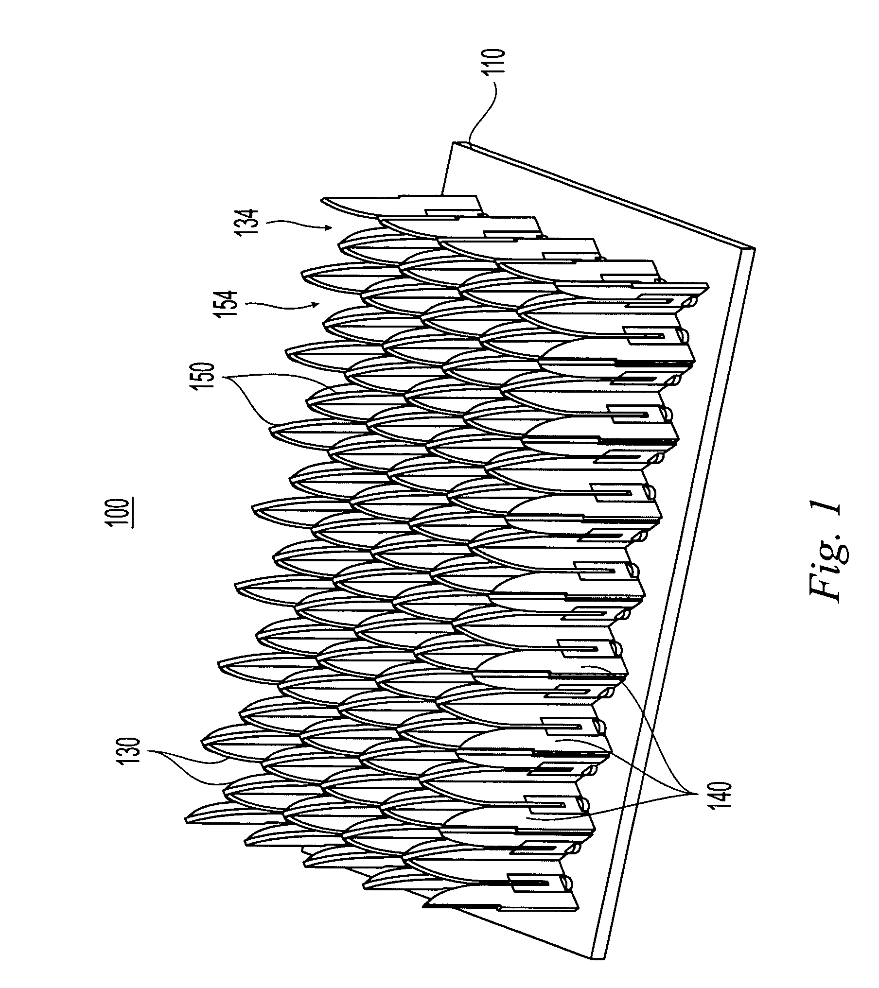
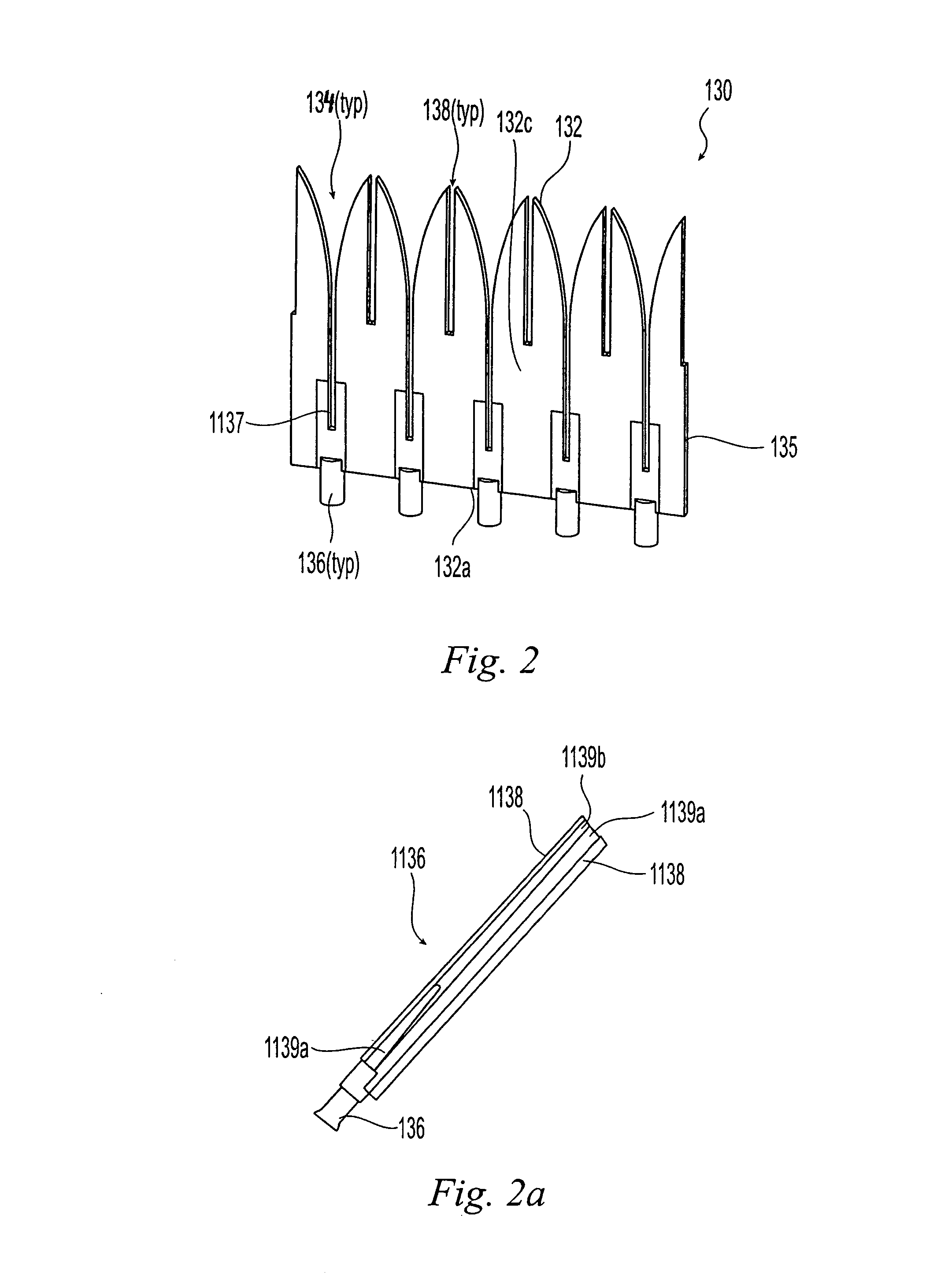
TEM horn array apertures are disclosed, comprises a plurality of stamped sheet segments interconnected to form an “egg crate” like array. Each stamped sheet comprises a plurality of TEM horn antennas with a series of cooperating slots, enabling the sheets to be assembled into an “egg crate” design that allows quick and inexpensive building of a TEM horn antenna array. Moreover, the stamped sheet segments are structurally and dimensionally stable, and thus the assembled array may be connected to a guide plane without the need for additional aligning or structural elements. A method of assembling the array is also disclosed.

Description

CROSS-REFERENCE TO RELATED APPLICATION[0001]This application is a continuation-in-part of U.S. nonprovisional patent application Ser. No. 10 / 290,733, filed Nov. 7, 2002, now U.S. Pat. No. 6,891,511 By Marc T. Angelucci, titled “Method of Fabricating a Radar Array,” the entire contents of which is incorporated herein by reference.FIELD OF THE INVENTION[0002]The present invention relates to the field of microwave antenna arrays.BACKGROUND[0003]As the frequency of operation of radar antennas increases, the spacing between the radiating elements that make up the aperture becomes smaller. For example, the spacing may be less than 1.0 cm (0.400″) center-to-center at 16 GHz (Ku band). In addition, effective phased array radars can have 10,000 or more radiating elements. The radiating elements in these assemblies have critical alignment requirements. They also require isolation between adjacent radiating elements and excellent grounding.[0004]Previous designs require manufacturing individua...

Claims


Application Information

Patent Timeline
Patent Type & Authority Patents(United States)
IPC IPC(8): H01Q21/26H01Q13/08H01Q21/06
CPCH01Q21/064H01Q13/08
Inventor ANGELUCCI, MARC T.
Owner LOCKHEED MARTIN CORP
Why Eureka
Try Eureka