Radio base station for wirelessly communicating with a radio terminal

a radio terminal and wireless communication technology, applied in the direction of wireless communication services, transmission monitoring, instruments, etc., can solve the problems of insufficient number of usable channels, inability to set the number of radio base stations installed in the communicatable area of each radio base station larger than the number of channels, and inability to install many radio base stations in the same area. , to achieve the effect of automatic modification of the optimum channel setting or cell setting quickly, and reducing interference between radio base stations

Inactive Publication Date: 2006-09-12
MAXELL HLDG LTD
View PDF12 Cites 13 Cited by
  • Summary
  • Abstract
  • Description
  • Claims
  • Application Information

AI Technical Summary

Benefits of technology

[0013]It is therefore an object of the present invention is to provide a radio base station which is one of radio base stations in a radio LAN, can solve the above problems in the prior art, minimize interference between the radio base stations. Even when interference occurs between the radio base station and a radio terminal wirelessly connected thereto, when external noise unexpectedly takes place or when the radio base station moves to another communicatable area; the base station of the present invention can automatically modify the optimum channel settings or cell settings quickly. Another object of the present invention is to provide a method for controlling the radio base stations.

Problems solved by technology

The radio LAN based on the aforementioned technique has a problem that, even in the case of the 2.4 GHz band or 5 GHz band, the number of usable channels is not sufficiently large and thus it is difficult to install many radio base stations in an identical area.
Even when the method is employed based on the above technique of automatically setting usable different frequencies for the respective radio base stations, it is impossible to set the number of radio base stations installable in the communicatable area of each radio base station larger than the number of channels.
Further, when many radio base stations are installed, interference takes place between the radio base stations and thus a desired performance cannot be secured.
However, since the most suitable location of the radio base station to be moved and installed is unknown, the movement and installation of the base station to the optimum point involves difficulties.

Method used


Image

  • Radio base station for wirelessly communicating with a radio terminal
  • Radio base station for wirelessly communicating with a radio terminal
  • Radio base station for wirelessly communicating with a radio terminal

Examples


Embodiment Construction

[0036]A radio base station in a radio LAN and a method for controlling the radio base station in accordance with an embodiment of the present invention will be explained in detail with reference to the accompanying drawings.

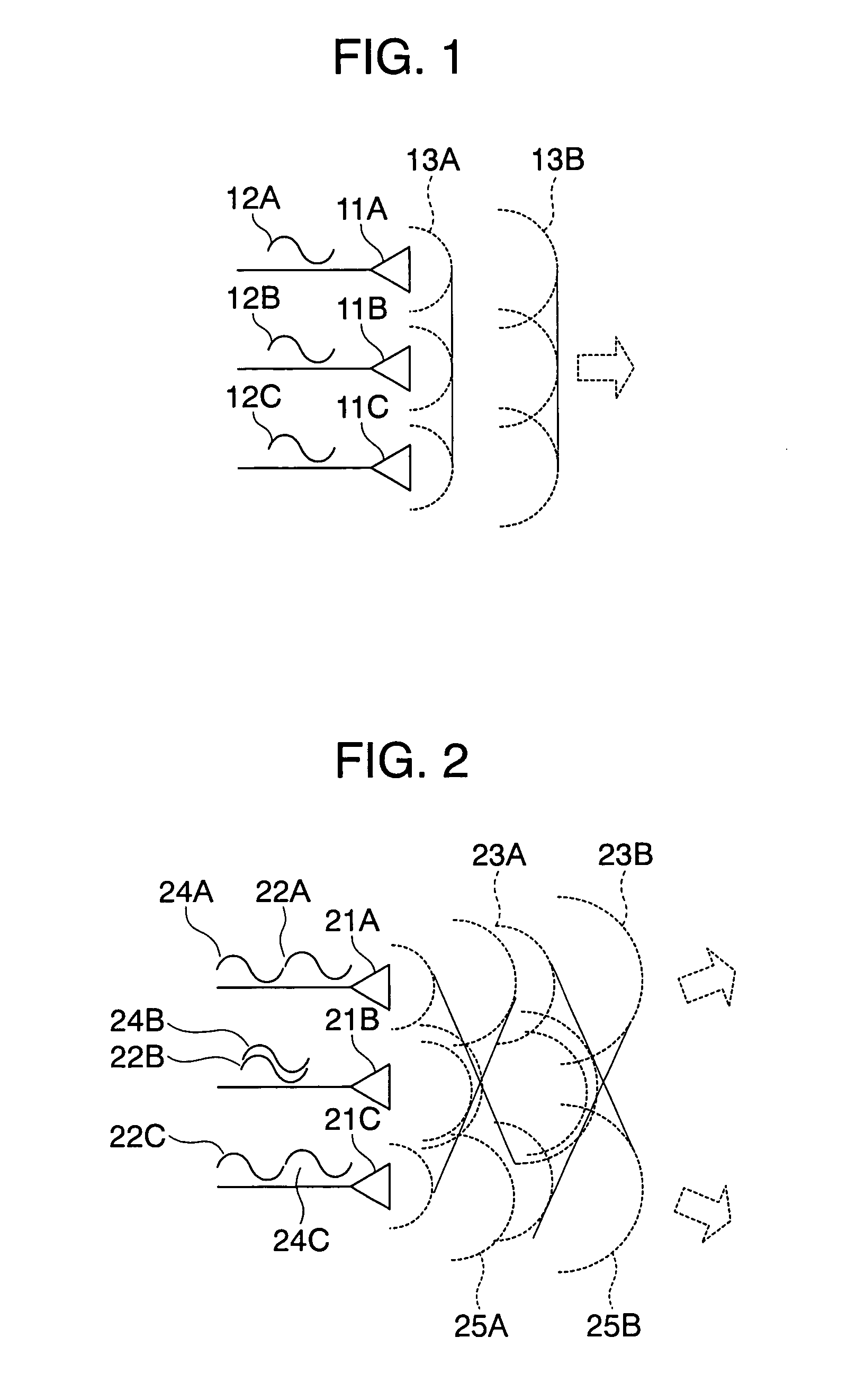
[0037]FIGS. 1 and 2 are diagrams for explaining directional antennas used in a radio base station in accordance with an embodiment of the present invention. In FIGS. 1 and 2, reference symbols 11A to 11C denote antennas, symbols 12A–12C, 22A–22C, and 24A–24C denote radio waves supplied to the respective antennas, 13A, 13B, 23A, 23B, 25A and 25B denote wave fronts radiated radio waves.

[0038]When it is desired for an antenna to have a directivity, it is a common practice to use a plurality of antennas at the same time. In the example of FIG. 1, the antennas 11A, 11B and 11C are arranged with an equal spacing therebetween, and the radio waves 12A, 12B and 12C are supplied in phase to the antennas. When the in-phase radio waves 12A, 12B and 12C are radiated from the ...


PUM


Abstract

A radio antenna of a radio base station is a directional antenna. The antenna searches for a peripheral radio base station by changing the directivity of the antenna. An operating channel and electric field intensity of the other base station are acquired by the searching and then stored as positional information. The operating channel of the base station, the directivity of the antenna, and a radio wave intensity communication area are set according to the acquired positional information. Further, the positional information is transmitted and received to and from the other base station to set the base station. When the base station was moved or when external noise occurred abruptly, channel change and change of a cell shape of the directional antenna are carried out. Consequently, interference between the base stations can be minimized and optimum setting of the channel and communicatable area can be realized.

Description

BACKGROUND OF THE INVENTION[0001]The present invention relates to radio base stations and methods for controlling the radio base stations and more particular, to a radio base station which can suppress interference between radio base stations connected to a wired LAN and interference caused by external noise and can enhance the performance of a wireless system, because such radio base stations automatically optimumly set their own communicatable ranges and operating frequencies. The present invention also relates to a method for controlling the radio base stations.[0002]At present, a wireless LAN is arranged generally based on a communication system using a direct spread (DS) system. The DS system is a technique for attaching a code monopolizing a specific frequency band to a signal, spreading and transmitting it. The number of radio terminals wirelessly connectable to a single radio base station is practically about 20. When it is desired to use about 20 or more of the radio termin...

Claims


Application Information

Patent Timeline
Patent Type & Authority Patents(United States)
IPC IPC(8): H04B1/00H04B15/00H04B1/707H04B1/7097H04B7/04H04L12/28H04W16/02H04W16/20H04W16/28H04W24/02H04W52/04H04W72/04H04W84/12H04W88/08
CPCH04B7/04
Inventor KASHIWAGI, KENJIMARUYAMA, TAKASHI
Owner MAXELL HLDG LTD
Why Eureka
Try Eureka