Disk device with clamp mechanism, attitude set-up member and conveying mechanism

a technology of clamping mechanism and drive plate, which is applied in the direction of magnetic recording, data recording, instruments, etc., can solve the problems of increasing load, device is difficult to be operated at a low load, and the load of sliding the slide plate is significantly large. achieve the effect of low load

Inactive Publication Date: 2006-09-12
ALPINE ELECTRONICS INC
View PDF6 Cites 14 Cited by
  • Summary
  • Abstract
  • Description
  • Claims
  • Application Information

AI Technical Summary

Benefits of technology

[0010]In order to solve the above-mentioned problems, the present invention has been made, and it is an object thereof to provide a disk device capable of

Problems solved by technology

However, since a conventional disk device having a linearly moving slide plate operates a clamping mechanism and an arm by sliding an inclined cam fabricated on the slide plate on the arm supporting the clamping mechanism and conveying rollers, the load for sliding the slide plate is significantly large.
Also, locking a mechanism unit using this slide plate increases the load when the slide plate is further operated.
Also,

Method used


Image

  • Disk device with clamp mechanism, attitude set-up member and conveying mechanism
  • Disk device with clamp mechanism, attitude set-up member and conveying mechanism
  • Disk device with clamp mechanism, attitude set-up member and conveying mechanism

Examples


Embodiment Construction

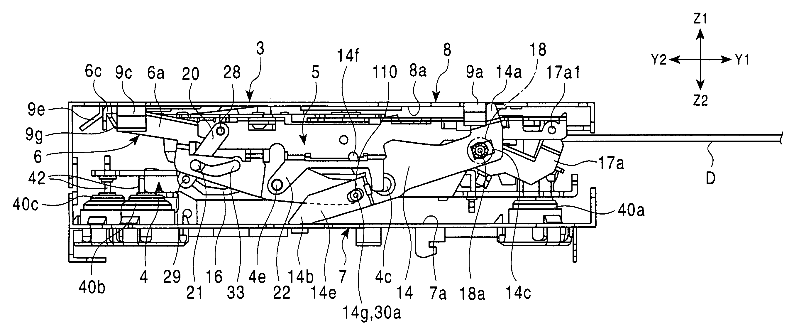
[0042]A disk device 1 according to the present invention can load a disk D such as a CD (compact disk) or a DVD (digital versatile disk). This disk device 1 is accommodated within a casing (not shown) with a size of one DIN. On the front surface of the casing, there is provided a face section (not shown) having a liquid crystal display panel and various switches, and the face section is provided with a slit loading slot extending in the width direction (X-direction).

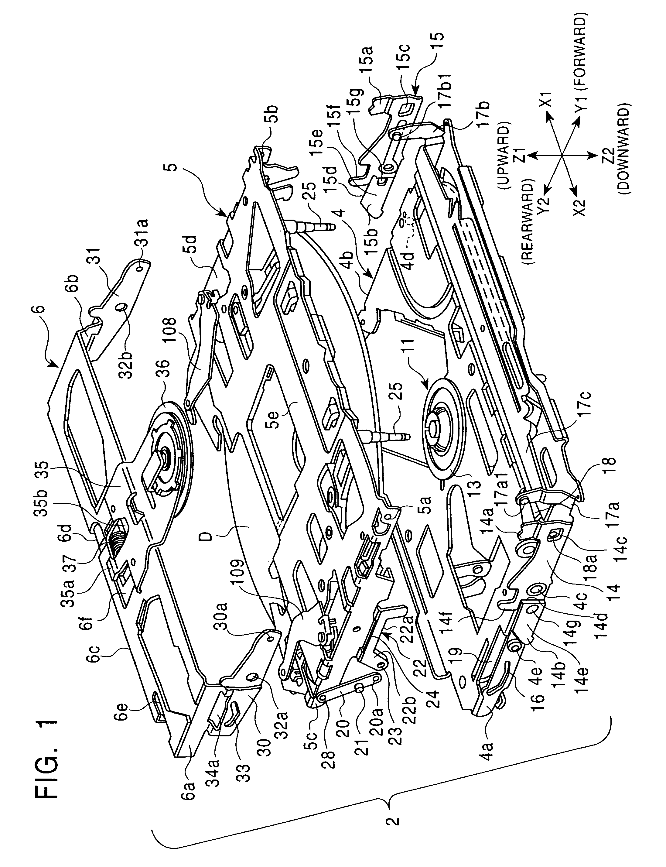
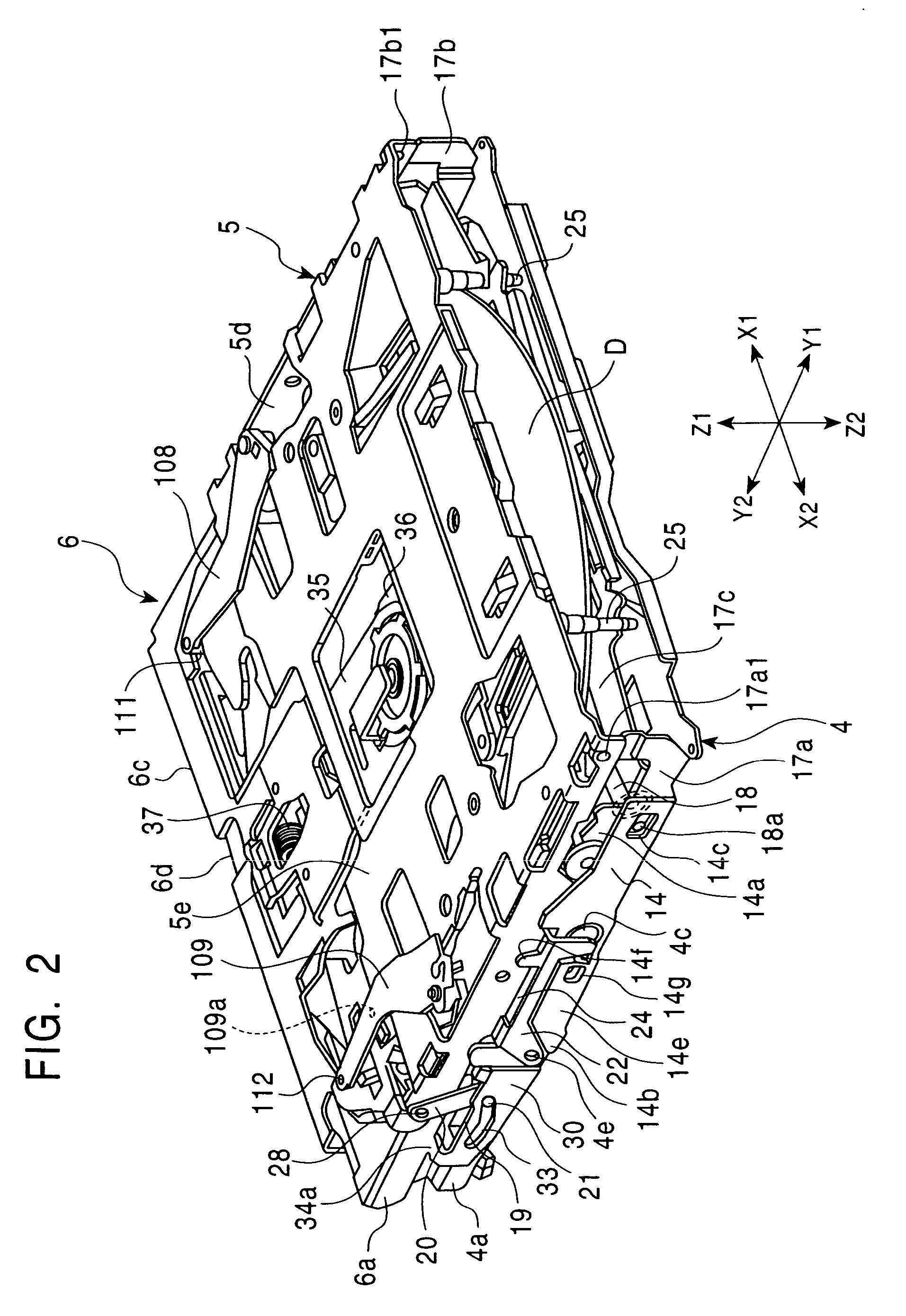
[0043]As shown in FIGS. 1 and 3, the disk device 1 includes a mechanism unit 2 and an external chassis 3 into which the mechanism unit 2 is accommodated. As shown in FIGS. 1 and 2, the mechanism unit 2 is composed of a lower chassis 4, an upper chassis 5, and a clamp chassis 6. Also, as shown in FIG. 3, the external chassis 3 is composed of a lower base 7 and an upper base 8.

[0044]As shown in FIG. 1, the lower chassis 4 is provided with a rotational drive unit 11 disposed at the center. The rotational drive unit 11 inclu...


PUM


Abstract

A disk device according to the present invention includes a mechanism unit having a rotational drive unit for driving a disk, a clamp mechanism for clamping the disk to the rotational drive unit, and a conveying mechanism for conveying the disk toward the rotational drive unit. The mechanism unit further includes an attitude set-up member, which is directly connected to the clamp mechanism and the conveying mechanism and rotates about an axis parallel to the surface of the disk mounted in the mechanism unit, and a drive mechanism for applying a rotational force to the attitude set-up member. When the attitude set-up member rotates in a predetermined direction, the clamp mechanism is operated to cancel the clamping of the disk, and the conveying mechanism is set to be able to convey the disk by the rotational force of the attitude set-up member. When the attitude set-up member rotates in a direction opposite to the predetermined direction, the clamp mechanism is set to clamp the disk, and the conveying mechanism is set not to apply a conveying force to the disk by the rotational force of the attitude set-up member. Thereby, the load for driving the clamp mechanism and the conveying mechanism can be reduced and these mechanisms can be timely operated.

Description

BACKGROUND OF THE INVENTION[0001]1. Field of the Invention[0002]The present invention relates to a disk device having a disk rotational drive unit and a disk conveying mechanism, and in particular relates to a disk device capable of switching between a clamp mechanism for clamping a disk to the rotational drive unit and a conveying mechanism.[0003]2. Description of the Related Art[0004]A vehicle-mounted disk device includes a disk rotational drive unit, a clamp mechanism for clamping a disk to the rotational drive unit, and a conveying mechanism for feeding the disk to the rotational drive unit, as a mechanism unit. Also, it is necessary to switch the transmission of a conveying force for the disk between the clamping operation of the clamp mechanism and the releasing operation of the clamp mechanism.[0005]The mechanism unit is supported by an elastic member, such as a damper, so as to prevent vehicle vibrations from being directly transmitted to the rotational-drive unit, preventin...

Claims


Application Information

Patent Timeline
IPC IPC(8): G11B17/043G11B19/20G11B17/051G11B17/04
CPCG11B17/056
Inventor TUCHIYA, TATUHIKO
Owner ALPINE ELECTRONICS INC
Why Eureka
Try Eureka